Vacuum Techniques
In this experiment you will learn about vacuum technology and how to use it for measurements
Experimental setup
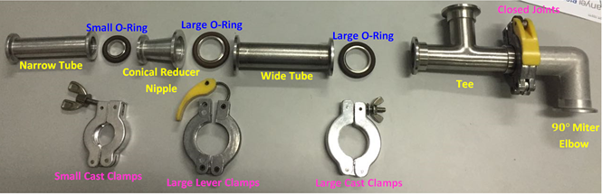
In this experiment you will build your vacuum system. You will have at your disposal the compenents shown in Figure 1.
In this experiment we shall use the following devices:
Rotary Vane Pump
Rotary Vane Pump is a pump that draws gas from a vacuum chamber to atmospheric pressure. It is made out of vanes mounted to a rotor, which rotates inside a cavity. The rotor is not aligned at the center of the cavity. The vanes are pressed against the cavity wall with the aid of springs and centrifugal force. The vanes form compartments that trap gas.A section view of a rotary pump is shown in Figure 2. For simplicity, only two vanes are shown, but there may be more than two. Oil is used to lower the friction between the vanes and the cavity. In addition, the oil serves as sealing matter, so gas will not flow between compartments.
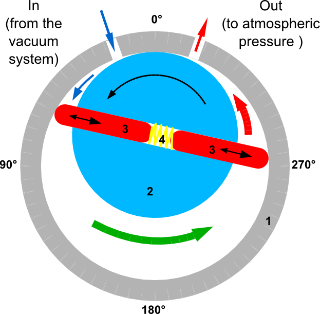
When the rotor turns the vanes, three types of compartments are formed:
- A compartment that grows so gas from the vacuum system is drawn in (indicated by blue arrow in Figure 2).
- A compartment that shifts the gas toward the exit port (indicated by green arrow).
- A compartment that shrinks so that gas from the previous compartment is pushed out to the atmosphere (red arrow).
As the rotor turns again and again, suction is formed, and gas moves from the system to the surroundings. Below is a video from YouTube illustrating the way the pump works:
Due to gas compression and friction, heat is generated in the vacuum system. Because of this, it is dangerous to touch the metal parts of the pump. In addition, you must remember that the pump contains oil. If a pump is turned off while connected to a vacuum chamber, oil may flow into the vacuum chamber. To avoid this contamination, a valve should be placed between the pump and the system. Before you power off the vacuum pump, the valve should be closed, and only then, should the pump be turned off and cautiously vented.
Piezoelectric Pressure Transducer
The piezoelectric effect, which is the appearance of an electric potential across certain faces of a crystal when it is subjected to mechanical pressure, was discovered by Pierre and Jacques Curie in 1880. It remained a mere curiosity until the 1940s. The properties of certain crystals to exhibit electrical charges under mechanical loading was of no practical use until very high input impedance amplifiers enabled engineers to amplify these signals. In the 1950s, electrometer tubes of sufficient quality became available, and the piezoelectric effect was commercialized.
The Curies discovered the phenomenon in quartz and Rochelle salt (KNaC4H4O6·4H2O) in 1880 and named the effect piezoelectricity (from Greek piezein, "to press"). The piezoelectric effect occurs in several crystalline substances including barium titanate and tourmaline. The converse is also observed: When an electric field is applied on certain faces of the crystal, the crystal undergoes mechanical distortion. These effects are explained by the displacement of ions in crystals in which the unit cells (the simplest polyhedron that makes up the crystal structure) lack inversion symmetry. When the crystal is compressed, the ions in each unit cell are displaced, causing the electric polarization of the unit cell. Because of the regularity of crystalline structure, these effects accumulate, causing the appearance of an electric potential difference between certain faces of the crystal. When an external electric field is applied to the crystal, the ions in each unit cell are displaced by electrostatic forces, resulting in the mechanical deformation of the whole crystal. Because of their capacity to convert mechanical deformation into electrical voltages, and electric voltages into mechanical motion, piezoelectric crystals are used in such devices as the transducer, record-playing pickup elements, and the microphone. Piezoelectric crystals are also used as resonators in electronic oscillators and high-frequency amplifiers, because the mechanical resonance frequency of adequately cut crystals is stable and well defined.
In a piezoelectric gauge, the pressure exerts mechanical force on the crystal and a voltage, which can be measured, appears as result. Because the crystal can be deformed by fluctuations of the room temperature as well, the lower limit of this gauge is approximately 1 Torr.
In the lab, you will use an APR250 model piezoelectric gauge from Pfeiffer Vacuum Company. Download its data sheet from here and look at the "Measurement range max." and "Measurement range min."values (note that you will not be able to use the entire range).
Take a look at some Vacuum Measurement Principles of the Piezo Gauge in this great video from Pfeiffer Vacuum. Pfeiffer Vacuum.Pirani gauge
The Pirani gauge is a robust thermal conductivity gauge used for the measurement of the pressures in vacuum systems. It was invented in 1906 by Marcello Pirani. The gauge is composed of heated wire (the wire is electrically heated) suspended in a gas medium. The wire is often called a filament. Gas molecules collide with the heated filament and, by heat convection, cool the filament. As a result, the filament reaches an equilibrium temperature. As the pressure drops, fewer gas molecules are available and less heat is taken from the filament. This causes the filament to heat up and reach a higher temperature. The temperature of the filament is proportional to the resistance of the filament, and, once a calibration curve is established for a particular type of gas molecules, the resistance can be used to calculate the pressure surrounding the filament.
In the lab, you will use an active TPR 280 Pirani transmitter from Pfeiffer Vacuum Company. Download its data sheet from here and look at the "Measurement range max." and "Measurement range min." (note that you will not use the entire range).
Take a look at some Vacuum Measurement Principles of the Pirani Gauge in this great video from Pfeiffer Vacuum. Pfeiffer Vacuum.Mass Flow Meter
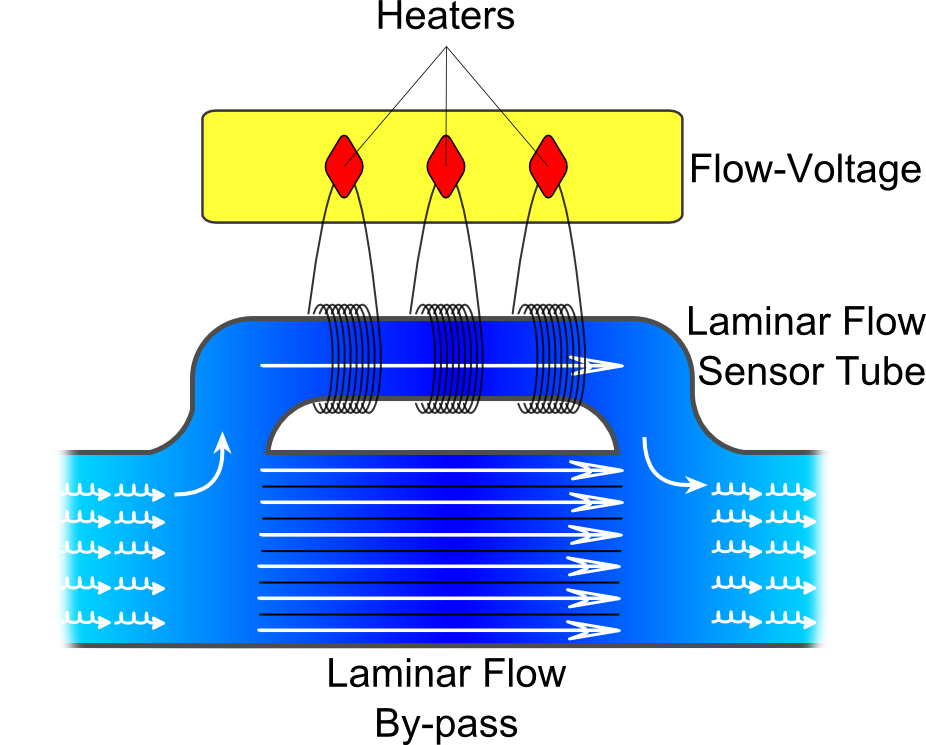
A mass flow meter (MFM) is used to directly measure mass flow, not volumetric flow. This is an important distinction in many applications since the mass flow rate (rather than volumetric flow rate) determines energy content and chemical reactivity. Volumetric flow measurement is less useful than mass flow measurement because a given mass of gas will change its volume with gas temperature and pressure. Mass flow measurements maximize process repeatability and testing accuracy. Mass flow rates, when used for gas flow measurements, are conventionally made in volumetric units. Since volume varies with temperature and pressure it is necessary to specify a volume at standard conditions. The schematics of the MFM is shown in Figure 3.