Inversion of light polarization by sucrose hydrolysis
In this experiment you will study the acid-catalyzed hydrolysis of sucrose.
Theoretical background
Introduction
In this experiment the rate of the reaction between sucrose and water, catalyzed by a hydrogen ion, will be determined by measuring the angle of rotation of polarized light passing through the solution. The angle of rotation of polarized light passing through the solution is measured using a polarized beam produced by a He-Ne laser and a polarizer. The reaction is:
Sucrose is dextrorotatory (i.e., it rotates the plane of a polarized light ray to the right relative to the oncoming radiation), but the resulting mixture of glucose and fructose is slightly levorotatory (i.e., it rotates the plane of the beam to the left). This is because the levorotatory fructose has a greater molar optical rotation than the dextrorotatory glucose. As the sucrose is consumed and the glucose-fructose mixture is formed, the angle of rotation is reduced until the polarization is rotated to the left.
The reaction of sucrose hydrolysis can be catalyzed not only by hydrogen ions but also by enzymes (for example, by ß-fructofuranosidase). The basic mechanism for enzyme catalyzed reactions was first proposed by Michaelis and Menten in 1913 and was confirmed by a study of the kinetics of the sucrose hydrolysis.
The experiment includes two parts. In the first part, you will learn about the properties of polarized light generated by a He-Ne laser. In the second part, you will study the chemical kinetics of the hydrogen ion-catalyzed inversion of sucrose.
Concepts you need to know:
- Plane of incidence
- Polarized light (linear and circular)
- Malus' Law
- Optical activity
- Chemical kinetics
- Specific rotation
- Operation principles of He-Ne laser, photodiode and polarizer
Part One
Plane of Incidence
Before we discuss phenomena like refraction and reflection in optics, the plane of incidence must be defined. In Figure 1, the blue arrow indicates the path of a light beam that hits a reflecting surface. The plane of incidence, shown in green, is defined by two vectors, the first is the vector normal to the reflecting surface and the second is the propagation vector of the light toward the reflecting surface. The plane of incidence contains a third vector, which is the propagation vector of the light from the reflecting surface.
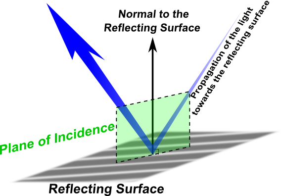
The incoming beam may be polarized parallel to the plane of incidence or vertically to it. In vertical polarization, the reflection from the surface will not lead to any change in polarization. In parallel polarization, there might be a change in polarization due to the reflection from the surface. This change, which is called the angle of rotation, will depend on the angle of incidence, and it will occur at the level of incidence.
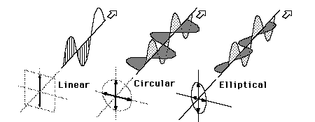
Classification of Polarization
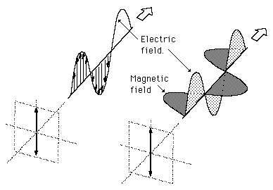
Light is an electromagnetic wave. An electromagnetic wave is a transverse wave, and as such it is actually composed of three distinct vectors that are perpendicular to each other: the magnetic field vector (B), the electric field vector (E), and the wavefront vector. As a result, an electromagnetic wave is defined based on its polarization. The polarization is determined by the direction of the electric field relative to the direction of the wavefront (Figure 2).
Light in the form of a plane wave in space is said to be linearly polarized. Light is a transverse electromagnetic wave, but natural light is generally unpolarized, all planes of propagation being equally probable. If light is composed of two plane waves of equal amplitude but differing in phase (of the plarization) by 90°, then the light is said to be circularly polarized. If two plane waves of different amplitude are related in phase by 90°, or if the relative phase is other than 90°, then the light is said to be elliptically polarized.
Linear Polarization
For a wave propagating in z direction, the electromagnetic wave is said to be linearly polarized when the direction of electric field wave is of the form of any of the following equations or any normalized linear combination of these:
The transverse electric field wave is accompanied by a magnetic field wave as illustrated in Figure 3. Don't confuse the magnetic field with the form of the circularly polarized light in Figure 2.
Circular Polarization
Circularly polarized light consists of two perpendicular electromagnetic plane waves of equal amplitude that differ by 90° in phase. An electromagnetic wave is said to be circularly polarized when the direction of electric field wave, is of the form of:
where (+) is for right-circularly polarized wave and (-) is for left-circularly polarized wave.
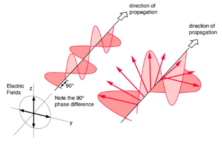
If you could see the tip of the electric field vector, it would appear to be moving in a circle as it approached you (Figure 4). If while looking at the source, the electric vector of the light coming toward you appears to be rotating clockwise, the light is said to be right-circularly polarized. If counterclockwise, then the light is left-circularly polarized. The light illustrated in Figure 4 is right-circularly polarized. The electric field vector makes one complete revolution as the light advances one wavelength toward you. Circularly polarized light may be produced by passing linearly polarized light through a quarter-wave plate at an angle of 45° to the optic axis of the plate.
Malus' Law
Let A be the amplitude of a plane polarized light beam incident on a polarizer.
Let us assume that the electric field of the polarized light is inclined at angle θ to the axis of polarizer; that is, the light is parallel to the x axis in the example shown in Figure 5.
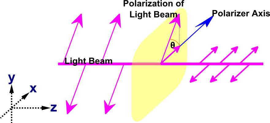
The component of A, Acosθ (component $\hat x$, which is parallel to the polarizer’s axis) is transmitted, whereas the component Asinθ (component $\hat y$, which is perpendicular to the polarizer’s axis) is blocked. Recall that the intensity is proportional to the square of amplitude, so the intensity transmitted is:
where $I_0$ is the intensity of light incident on the polarizer.
If unpolarized light, $I_u$, falls on the polarizer, ideally only half of the light (i.e., $I_u/2$) will be transmitted:
The field of the incident wave has components parallel and perpendicular to the polarizing axis. The incident light is a random mix of both so each component is equal. If a second polarizer is placed in front of the beam, with an orientation of θ relative to the first polarizer, the intensity transmitted is given by the following equation:
Note that the polarization direction of the light after passing through the polarizer is identical to the polarizer's orientation; however, the intensity is reduced according to Malus' law. When a polarized light passes through an optically active substance the polarization direction changes, but the intensity remains unchanged.
Refer to the Open Source Physics website where you will find few Java applets. The Polarizer program displays the effect of a plane polarizer on an incident electromagnetic wave. The polarization of the electromagnetic wave and the orientation of the polarizer can be modified.
Part Two
Optically active compounds
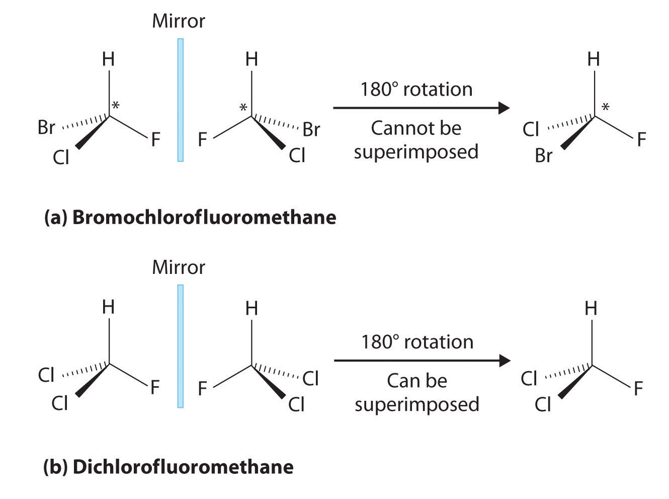
Two compounds are called isomers if they have the same molecular formula but different chemical structures. Optical isomers are those in which two compounds have not only the same molecular formula but also identical bonding connections among the atoms that make up the molecule. The optical isomers in a pair are distinct from each other, however, because they are nonsuperimposable mirror images of each other. One optical isomer cannot be superimposed on the other, just as your left hand cannot be superimposed on your right hand. Compounds that exist as optical isomers are frequently referred to as chiral compounds, and each of the pair of optical isomers is called an enantiomer. Molecules such as $H_2O$ and $CH_4$, which do not exist as nonsuperimposable pairs, are called achiral. A few examples of chiral compounds are presented in Figure 6.
If plane polarized light is passed through a solution of a chiral compound, the plane of polarization of the light is rotated either clockwise or counterclockwise. The extent of this rotation depends on the nature of the compound, the path length of the solution, and the environmental factors such as temperature. Under the same conditions, enantiomers rotate light to the same extent, except that one rotates the plane of polarized light to the left and the other structure rotates it to the right.
As chiral compounds rotate light, they are often called optically active compounds. A solution of achiral molecules is optically inactive; however, achiral compounds may exhibit optical activity when organized in certain symmetries. The reason chiral compounds rotate polarized light is complex and is fully explained only by a quantum mechanical treatment of the interaction of electromagnetic radiation with chiral compounds. One way of thinking about optical rotation, however, is to consider linearly polarized light as a superposition of right-handed and left-handed circularly polarized light. Because circularly polarized light has a handedness, just as chiral molecules do, it is not surprising that right- and left-handed circularly polarized light interact differently with chiral molecules. Specifically, the index of refraction of a chiral substance is different for left- and right-handed circularly polarized light: The right- and left-handed components of linearly polarized light travel through a chiral medium with different velocities, and one handedness of light is retarded with respect to the other. The net effect of this retardation is to rotate the direction of the polarization of the linearly polarized light.
No easy method can predict whether a particular chiral compound will rotate light clockwise or counterclockwise. Distinguishing between two enantiomers by the direction in which they rotate the polarization of light is often convenient, however. By convention left-rotating enantiomers are labeled (-) and right-rotating ones (+). Some chiral compounds rotate light more than others, and chiral compounds can be assigned to specific rotation values (often designated in tables by the symbol [α]), which reflects the extent to which the compound rotates light. The specific rotation is defined as:
where α refers to the rotation (in degrees) of the electric field vector that occurs as the light travels a distance ℓ (in decimeter) through a solution with a concentration c (in g/mL; note that g/mL means 1 gram of compound per 1 mL of the total solution!).
The specific rotation of a solution is not dependent on the concentration of the solution. The specific rotation of a solution does depend, however, on the temperature of the solution and on the wavelength of light traveling through it. Thus, specific rotations are often labeled with a superscript that indicates the temperature (in °C) and a subscript that indicates the wavelength of light (in nm). Therefore, specific rotation of the solutions in this experiment should be reported as:
because the experiment will be performed at 25 °C and the light produced by a red He-Ne laser is 632.8 nm. The bottle that you will get in the lab will be marked by $[α]^{25}_D$; the subscript D means 589 nm Na-D-line standard appropriate for us at 25 °C. In 1815 Jean Baptiste Biot found the optical rotation to be inversely proportional to the square of the wavelength. You can find the exact equation in the experimental procedure.
Chirality in Organic Chemistry and Biological Chemistry
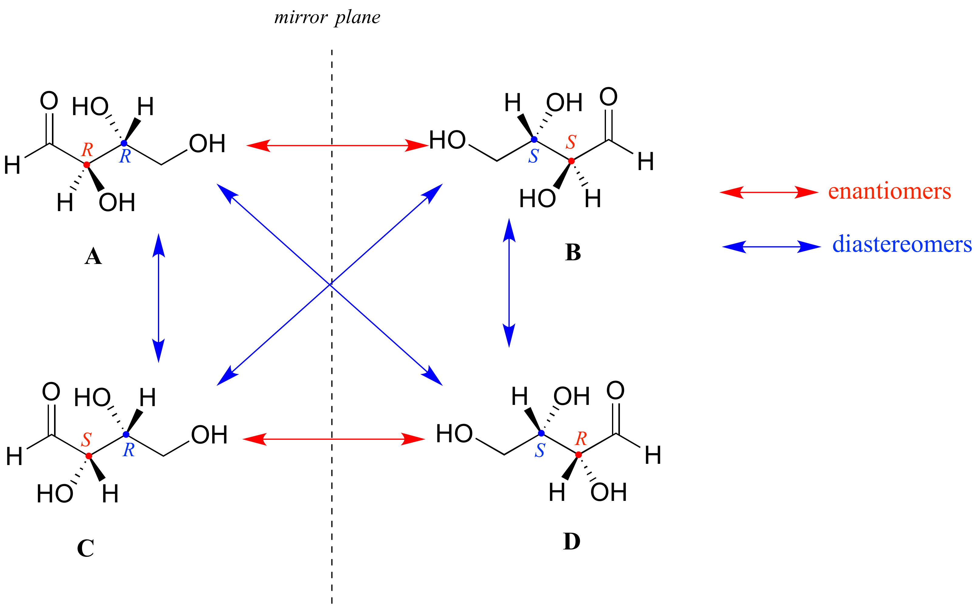
Chirality is an especially important concept in organic chemistry, because a vast number of organic compounds are chiral. The chiral nature of organic compounds usually results from an asymmetric carbon atom that is bonded to four different substituents. A simple example of a chiral organic molecule is shown in Figure 7. The enantiomers can be thought of as having two of the attached atoms reversed, causing the two forms to be nonsuperimposable. Many organic compounds have more than one asymmetric carbon, each of which is called a chiral center. In these compounds each chiral center adopts one of two possible configurations. Therefore, for a molecule with n chiral centers there are 2n total possible configurations. Some of these configurations are mirror images of each other and are called enantiomeric pairs. Any given pair of configurations are not necessarily mirror images, and in general these possible configurations are called diastereomers. Chemists need a convenient way to distinguish one stereoisomer from another. The Cahn-Ingold-Prelog system is a set of rules that allows us to unambiguously define the stereochemical configuration of any stereocenter, using the designations 'R ’ (from the Latin rectus, meaning right-handed. Also known as D-isomers.) or ' S ’ (from the Latin sinister, meaning left-handed. Also known as L-isomers.).
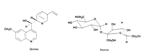
The vast majority of important biological compounds have at least one chiral center. Sucrose for example has 9 chiral centers. The structures of sucrose and quinine are shown in Figure 8.
Amino acids and sugars have a special labeling system to distinguish between different diastereomers: The letters D and L, from the Latin dexter (right) and laevus (left), are used to indicate how the -H and -OH groups are attached to a particular carbon atom. Despite their names, the labels do not indicate the way the light is rotated. Interestingly, in most life forms, only L forms of amino acids are produced, whereas the D forms of sugars predominate. Although there is no intuitive reason for one configuration to predominate over the other, biological systems have evolved such that for many chiral compounds, only one isomer is observed in nature. This fact has profound implications for the pharmaceutical industry: Many drugs have chiral centers, and in many cases only one of the enantiomers has the desired biological activity. In fact, different isomers of the same drug can have entirely different effects on the body. One isomer of a drug may have the desired healing effect, but the other may have no effect or even be harmful. Thus, controlling the chirality of biological compounds when they are being synthesized is almost always necessary, and analysis of chirality presents a key challenge for the pharmaceutical industry in developing safe and effective drugs.
Specific Rotation
Determination of Specific RotationThe observed rotation is dependent upon the path length of the light passing through the sample compartment and is also dependent upon the number of molecules of the isomer. The observed rotation is converted to a specific rotation by using formula presented in equation (7). Let us take as an example the following case. Suppose that an optically active isomer produced an observed rotation of +13.00 degrees. The sample had a concentration of 1000 g/L and the sample tube was 20 cm in length. What would be the reported specific rotation of this dextrorotatory isomer?
- Convert the concentration to g/mL:
1000 g/L X 1 L / 1000 mL = 1.0 g/mL
- Convert the length of the tube to decimeters knowing that 10 cm = 1 decimeter:
20 cm X 1 dm / 10 cm = 2 dm
- From equation (7) calculate the observed specific rotation [α]:
[α] = +13.00 deg/ (1.0 g/mL) (2 dm) = +6.50 deg·g-1·ml·dm-1
Here is another example: Suppose that the observed rotation was -45.5 degrees. The concentration was 3.00 g/mL and the length of the tube was 20 cm. Determine the specific rotation. Is this a dextrorotatory or levorotatory isomer?
- Convert the length of the tube to dm:
20 cm X 1 dm / 10 cm = 2 dm
- Calculate [α]:
[α] = -45.5 degrees / (3.0 g/mL) (2 dm)= -7.58 deg·g-1·ml·dm-1
- Since the rotation is negative this is the levorotatory isomer.
Chemical Kinetics
Chemical kinetics describes a field of research that aims to determine the rate and characteristics of reactions. It can provide insight into the molecular origin of chemical reactions and is related to various thermodynamic parameters such as chemical equilibrium constants. By combining models with experiments, chemists are able to understand how chemical reactions take place at the molecular level.
First-Order Reactions
First-order reactions are characterized by the property that their rate is proportional to the amount of the reactant. It follows that the differential rate law contains the concentration of the reactant and a proportionality constant (the rate constant):
where [A] is the concentration of reactant A, t is time, and k is a constant.
Mathematicians call equations that contain the first derivative but no higher derivatives first-order differential equations. Chemists call the equation d[A]/dt = -k[A] a first-order rate law because the rate is proportional to the first power of [A] (that is, the change in the concentration of A is linearly dependent on its concentration at any time point). Integration of this ordinary differential equation is elementary, giving:
A common way for a chemist to discover that a reaction follows first-order kinetics is to plot the measured concentration versus the time on a semi-log plot. Namely, the concentration versus time data are fit to the following equation:
A plot of ln([A]) versus t is a straight line with slope -k. Alternatively, a plot of rate versus [A] is a straight line with slope -k. From experimental data the rate constant can be found from the slope of the appropriate plot.
Second-Order Reactions
Second-order reactions are characterized by the property that their rate is proportional to the product of two reactant concentrations, or to the square of one concentration if only one reactant is involved in the reaction. Suppose that the reaction of A to form products is second order in A or that the reaction of A with B to form products is first order in A and also first order in B. Then the differential rate laws in these two cases are given by:
In mathematical language, these are first-order differential equations because they contain the first derivative and no higher derivatives. A chemist calls them second-order rate laws because the rate is proportional to the product of two concentrations. By elementary integration of these differential equations integrated rate laws can be obtained:
or
where [A]0 and [B]0 are the initial concentrations of A and B (assuming $[A]_0 ≠ [B]_0$), and ξ is the extent of reaction at time t (extent of reaction: a quantity that measures the extent in which the reaction proceeds). Note that function (16) can also be written as:
A common way for a chemist to discover that a reaction follows second-order kinetics is to plot 1/[A] versus the time in the former case or $ln([B]_0([A]_0-x)/[A]_0([B]_0-x)$ versus time in the latter case.
A plot of 1/[A] versus t is a straight line with slope k.
Using the Specific Rotation to Find Rate Constants
Equation (7) describes the relationship between the specific rotation of a substance and its rotation when present at a given concentration [g/mL] with a specific length of the beam path.
In any reaction, the concentration of a substance (c) is dependent on time (t) so we can write:
From the stoichiometry of the reaction shown in equation (1), we can conclude that the concentration [in mol/L or M] of the fructose and glucose at any time, t, is equal to:
where cs(t), cf(t), cg(t) are the concentrations of sucrose, fructose and glucose, respectively, as a function of time and cs(0) is the initial concentration of sucrose. Fructose and glucose have the same molecular weights (MW) so in order to transform units of molar concentration to [g/mL] we can write:
If we substitute equation (22) into equation (20), we get a set of equations describing the rotation angle as a function of time for each substance:
Bear in mind that at any given time of the reaction, the rotational angle of a solution is the sum of the rotational angles of each component, so if one substitutes $α_s(t), α_f(t)$ and $α_g(t)$ into the expression {α(t)—α(∞)}/{α(0)—α(∞)} one obtains:
By substituting equations (22), (23) and (24) into equation (25), we obtain (after some algebra) the following:
Since the reaction of the sucrose is a first-order reaction:
Now we have the relationship between the time and the rotational angle of the solution and from that we can calculate the rate constant, k, of the reaction.
Experimental Equipment and Principles
Principles of Lasers
Let us consider a collection of atoms or molecules interacting with an electromagnetic wave that is propagating along the z axis. If the wave is of appropriate frequency to cause stimulated transitions in the system, each stimulated emission generates a photon and each absorption removes a photon. The change in radiant flux dΦ with the distance dz due to absorption is given by $dΦ=—Φniσ·dz$, where σ is the transition cross-section in cm2. The change in flux due to stimulated emission in distance dz is $dΦ=Φnjσ·dz$. Thus we can write the total change in radiant flux in distance dz as:
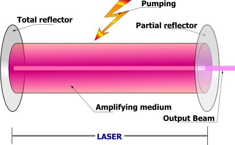
This equation shows that there is a net gain in a flux when $(n_j>n_i)$. When the system is at thermodynamic equilibrium, $(n_j)_{eq} <(n_i)_{eq}$, the medium is absorbent. However, if the upper level population can be made to exceed that of the lower level $n_j>n_i$, the system behaves like an amplifier at frequency $ν_{ij}$. Under this condition, the atomic or molecular system is called an active medium, and it has undergone population inversion. In the IR-to-visible frequency region, such an amplifier is called a laser (for Light Amplification by Stimulated Emission of Radiation). The population inversion can be achieved by excitation of the active medium by external source. The excitation process, called pumping, can be by optical methods with other sources, by electrical methods using an electrical discharge, by chemical reaction or by rapid adiabatic expansion. In a laser device, the amplifier is located between two (or more) mirror resonators, which provide positive feedback if a wave that performs a roundtrip inside the resonator undergoes constructive interference. Figure 9 shows a schematic of a laser device.
He-Ne laser
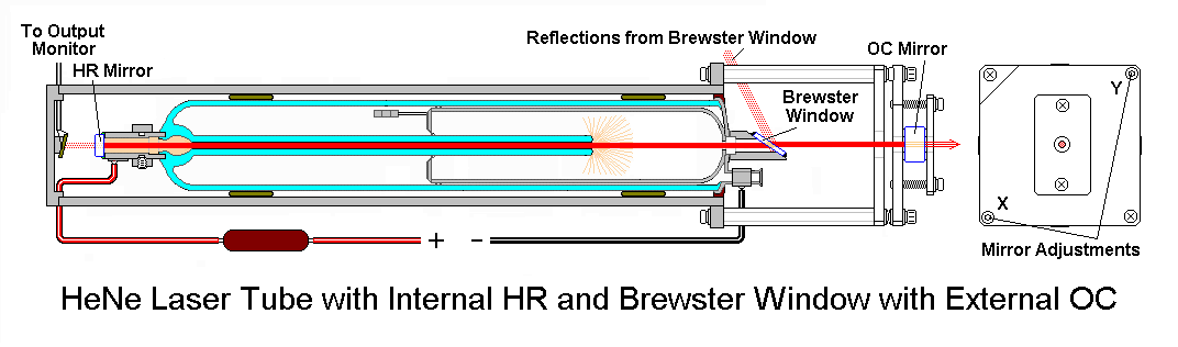
The He-Ne laser is the most common of all lasers. It is a continuous wave (or CW) laser pumped by electrical discharge. The lasing transitions occur between the Ne energy levels, and He is added to increase the pumping efficiency. The helium atoms are ionized to maintain the discharge. Metastable levels in He atoms transfer energy efficiently to Ne. The dominant laser transitions are at 632.8 nm, 1.15 µm, and 3.39 µm. The outputs of many He-Ne lasers as well as other noble gas lasers are linearly polarized. This can be understood from the scheme of He-Ne laser shown in Figure 10.
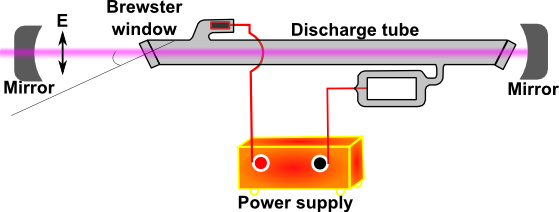
Figure 10 shows polarized output of the He-Ne laser. The discharge tube is terminated by end windows titled at Brewster’s angle (explained in the next paragraph). Thus no reflections occur at the windows for light polarized with the electric field vector in the plane of the figure. The orthogonal component is partially reflected on each pass and quickly becomes an insignificant part of the output beam. Simple He-Ne lasers made for use as alignment aids are available without Brewster angle windows and thus with unpolarized outputs. The He-Ne laser is simple and inexpensive. The output power is limited, however, to the range 0.5-50 mW because at low currents few metastable ions form, whereas at high currents the He atoms ionize (take a look at this Wikipedia article to understand why this is important).
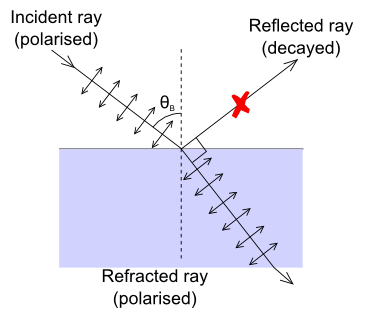
Brewster’s Angle
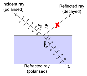
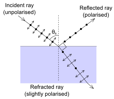
If the incident ray is polarized in such a way that its electric field oscillates only in the plane perpendicular to the refraction plane then the intensity of the reflected ray depends very strongly on the incidence angle. In the extreme case when directions of the reflected ray and polarization of the refracted ray are parallel (Figure 11), intensity of the reflected ray becomes equal to zero. The angle between the reflected ray and refracted ray in this case is equal to 90°, and the incidence angle is called Brewster's angle. The refraction index can be calculated from Brewster's angle αB using Snell's law (follow the link to a Wikipedia article for more information) because $α_B = 90° - β$.
The schematic illustrations in Figure 12 explain how the Brewster window enables the laser beam to become polarized. This happens in a time scale of a second or so.
Polarizers
Different types of filters result in polarization of laser light. These filters can be categorized as linear polarizers, retarders and circular polarizers.
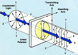
LINEAR POLARIZERS: Synthetic linear polarizing filters (polarizers) possess special properties for selectively absorbing light vibrations in certain planes. When unpolarized light, which is a complex mixture of vibrations lying in all possible directions transverse to the line of travel, is passed through a linear polarizer, its vibrations become confined to a single linear plane and the light is considered "polarized". This linearly polarized light can be modified to suppress unwanted reflections and to eliminate glare for a variety of applications.
RETARDERS: Optical retarders are polarization form converters. They are made from clear, oriented polyvinyl alcohol film laminated to a cellulose acetate butyrate substrate. The retarder has two principal axes, slow and fast, and it resolves a light beam into two polarized components (the one parallel to the slow axis lags the one parallel to the fast axis), and then recombines the two to form a single emerging beam of a specific polarization form. Retarders are used mainly to produce circular polarization when used with a linear polarizer.
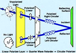
CIRCULAR POLARIZERS: A circular polarizer is comprised of a linear polarizer and a 1/4 wave retarder with slow and fast axes at 45° to the axis of the polarizer. A ray of unpolarized light passing through the linear polarizer becomes polarized at 45° to the axis of the retarder. When this polarized light ray passes through the retarder its vibration direction is made to move in a helical pattern. After the light ray is reflected from a specular surface, the sense of rotation of the vibration reverses. This rotation is stopped in the return through the retarder. The result is that light ray is linearly polarized in a plane 90° to its original polarization plane, and it is absorbed by the linearly polarized component of the circular polarizer as shown in Figure 14.
Photodiodes
Photodiodes are semiconductor light sensors that generate a current or voltage when the P-N junction in the semiconductor is illuminated by light. The term photodiode can be broadly defined to include solar batteries, but it usually refers to sensors used to detect the intensity of light. Photodiodes can be classified by function and construction.
Operation Principle of Photodiodes
Figure 15a shows a cross section of a photodiode. The PN junction operates as a photoelectric converter. The usual P-layer for a silicon photodiode is formed by selective diffusion of boron to a thickness of approximately 1 µm or less. The neutral region at the junction between the P- and N-layers is known as depletion layer. The N-layer is the substrate layer. By varying and controlling the thickness of the outer P- layer, the N-layer, and the bottom N+-layer as well as the doping concentration, the spectral response and frequency response can be controlled.
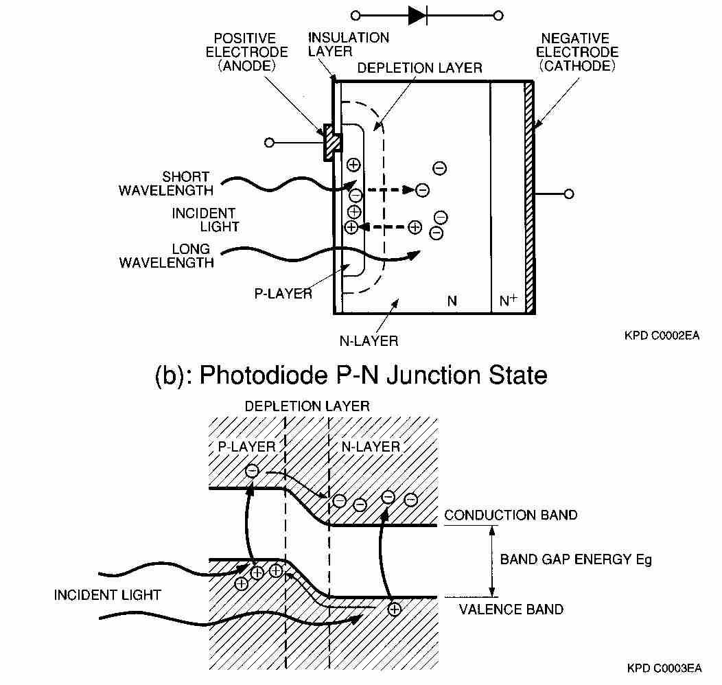
When light strikes a photodiode, the electrons within the crystal structure become stimulated. If the light energy is greater than the band gap energy Eg, the electrons are pulled up into the conduction band, leaving holes in their place in the valence band (Figure 15 b). These electron- hole pairs occur throughout the P-layer, depletion layer, and N-layer materials. In the depletion layer the electric field accelerates these electrons toward the N-layer and the holes toward the P-layer. Of the electron-hole pairs generated in the N-layer, the electrons, along with electrons that have arrived from the P-layer, are left in the N-layer conduction band. The holes diffuse through the N-layer up to the depletion layer while being accelerated and collected in the P-layer valence band. In this manner, electron-hole pairs, which are generated in proportion to the amount of incident light, are collected in the N- and P-layers. This results in a positive charge in the P-layer and a negative charge in the N-layer. If an external circuit is connected between the P- and N-layers (Figure 15a), electrons will flow away from N-layer, and holes will flow away from the P-layer, toward the opposite respective electrodes.