Interferometry
In this experiment you will study photon interference using a Mach-Zehnder and a Michelson interferometer.
Experimental Setup
In this experiment you will use various optical devices and components. A brief introduction to the experimental setup is provided here. You are however, encouraged to read more about the devices.
Monochromatic Interference (With a Laser Source and Mach-Zehnder Interferometer)
This part of the experiment will be executed with the setup in the following figure:
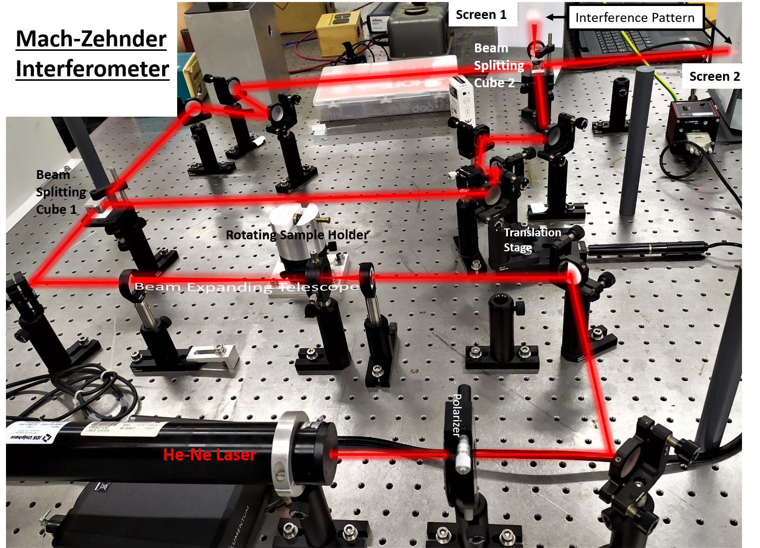
The output beam from the He-Ne laser is splitt into two beams at the first beam splitting cube. One beam is transmitted, while the second beam is reflected. The reflected beam passes through a sample (held by the rotating sample holder) and reaches the mirrors on the translation stage. The translation stage enables elongation and shortening of the optical path of this arm in comparison to the constant optical path of the trasmitted arm. Both arms pass through a few mirrors, allowing:
- Modification of the optical paths' lengths. Since the interference pattern is achieved when the electric fields of the arms overlap in time, they must pass equal distances (since Δt=Δx/c where c is the speed of light).
- Easier alignment of the arms for better spatial overlap between the beams.
After reaching the second beam splitting cube, each arm is split into a transmitted and a reflected beam. The transmitted beam of one arm overlaps the reflected beam from the second arm, and their interfernce can be observed on the screen.
Additional optical components in the setup that are not an integral part of the interferometer:
- A polarizer at the output of the laser, for attenuation of its intensity.
- A beam expanding telescope, consisting of two focusing (convex) lenses with different focal lengths. An iris is placed at the focal point of both lenses and used for modifications of the beam's image.
- Each arm passes through a few mirrors, for the reasons mentioned above.
- The concave lens that is located after the second beam splitter diverges the beams and enables better observation of the diffraction pattern.
White Light Interferometry (using a Michelson Interferometer)
This part of the experiment will be executed with the setup in the following figure:
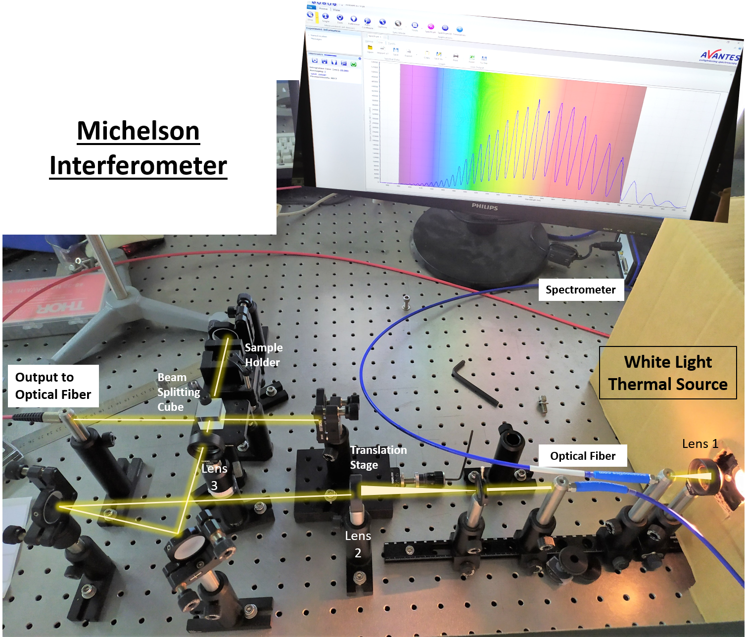
In order to achieve a clear image of the white light, the output beam from the thermal source is focused by Lens 1 into an optical fiber (blue). Afterwards, it is collimated by lens 2. The beam is split into two components: reflected and transmitted, at the beam splitting cube (Lens 3 is positioned before the cube for better alignment). One of the arms (the reflected one, in this case) is reflected back to the cube by a mirror on a translation stage, this is the "dynamic" arm. The transmitted part of the beam passes through a sample holder and is reflected back to the cube by a mirror; this is the "static" arm. After passing the cube for the second time, each arm is split into two components. The interference we observe is of the transmission of one arm with the reflection of the second, entering the optical fiber (red) to a spectrometer. In this setup, instead of directly observing the spatial interfernce between the arms (as in the Mach-Zehnder setup), you will obtain information about the interference in the frequency domain by observing the wavelength spectrum.