Conductance of Solutions
In this experiment you will learn about the electrical conduction properties of aqueous solutions.
Experimental Setup
Equivalent electrical circuit
In order to simplify the treatment of the electrochemical cell, we wish to draw its equivalent electrical circuit. The first step is to understand the processes that occur at the electrode's surface when electrical potential is applied to it:
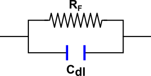
- Double layer - ions whose charge is opposite to that of the electrode accumulate near the surface. The accumulated charge screens the electrode from the solution. The double layer can be described as a capacitor: the two plates, in this case, are the surface charge on the electrode surface and the diffuse layer of ions near the surface. The capacitance of the double layer is denoted Cdl.
- Faradaic reaction - involves the transfer of charge through the interface at the electrode's surface. The Faradaic reaction is associated with a resistance, RF. Read more about the Faradaic effect here.
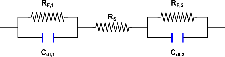
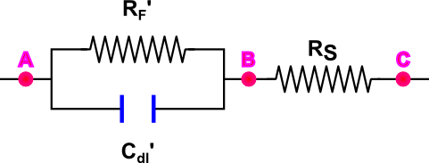
Figure 1 shows an equivalent circuit of a single electrode. The resistance of the solution to the motion of ions can be taken into account introducing a series resistance, Rs. The equivalent electrical circuit for the cell (two electrodes and solution between them) is presented in Figure 2. Finally, in the case of two identical electrodes the electrical circuit can be simplified. We replace the two resistances and capacitances with equivalent values, RF' and Cdl', to make the circuit look as in Figure 3.
Remember! The circuits drawn in these figures are only equivalent circuits, representing the solution and electrodes, and not the circuit you will use during the experiment!
The presence of the double layer and Faradaic reactions makes measuring the ionic conductivity in the cell (represented above as the resistance, RS) more difficult. There are several ways to minimize the effect of these processes:
- Using a high frequency alternating current (AC) minimizes the double layer. The quantity of electrical charge carried during one half-cycle is insufficient to produce any measurable polarization of the electrode. With an increase of the current's frequency the resistance between points A and B decreases, and the total resistance measured between points A and C approaches the resistance of the solution RS.
- Employing platinum electrodes covered with a colloidal deposit of "platinum black", having an extremely large surface area, to facilitate the adsorption of the tiny quantities of electrode reaction products produced in one half-cycle. This diminishes the effect of the Faradaic reactions.
Two-electrode cell
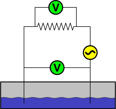
In this setup, two electrodes are connected to the power source, with a known resistor connected in series. One voltmeter measures the potential on the electrodes, and a second voltmeter measures the potential on the resistor. The current passing through the circuit can be calculated from the readings of the second voltmeter. The overall resistance between the electrodes calculated by knowing the current and potential on them. Figure 4 shows this setup.
Four-electrode cell
The two-electrode cell is susceptible to Faradaic reactions, since the solution potential is measured by the same electrodes passing the current to the solution. One way to solve this problem is to use four electrodes: one pair is used to measure the potential, while the other passes the current. This setup, called a four-electrode cell, is shown in Figure 5. The "in" electrodes are used to pass current through the solution, and a voltmeter attached to a resistor with known resistance measures it. The "out" electrodes are used to measure the potential. Knowing both the current and potential, the solution's resistance can be calculated.
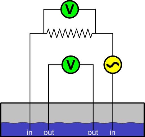
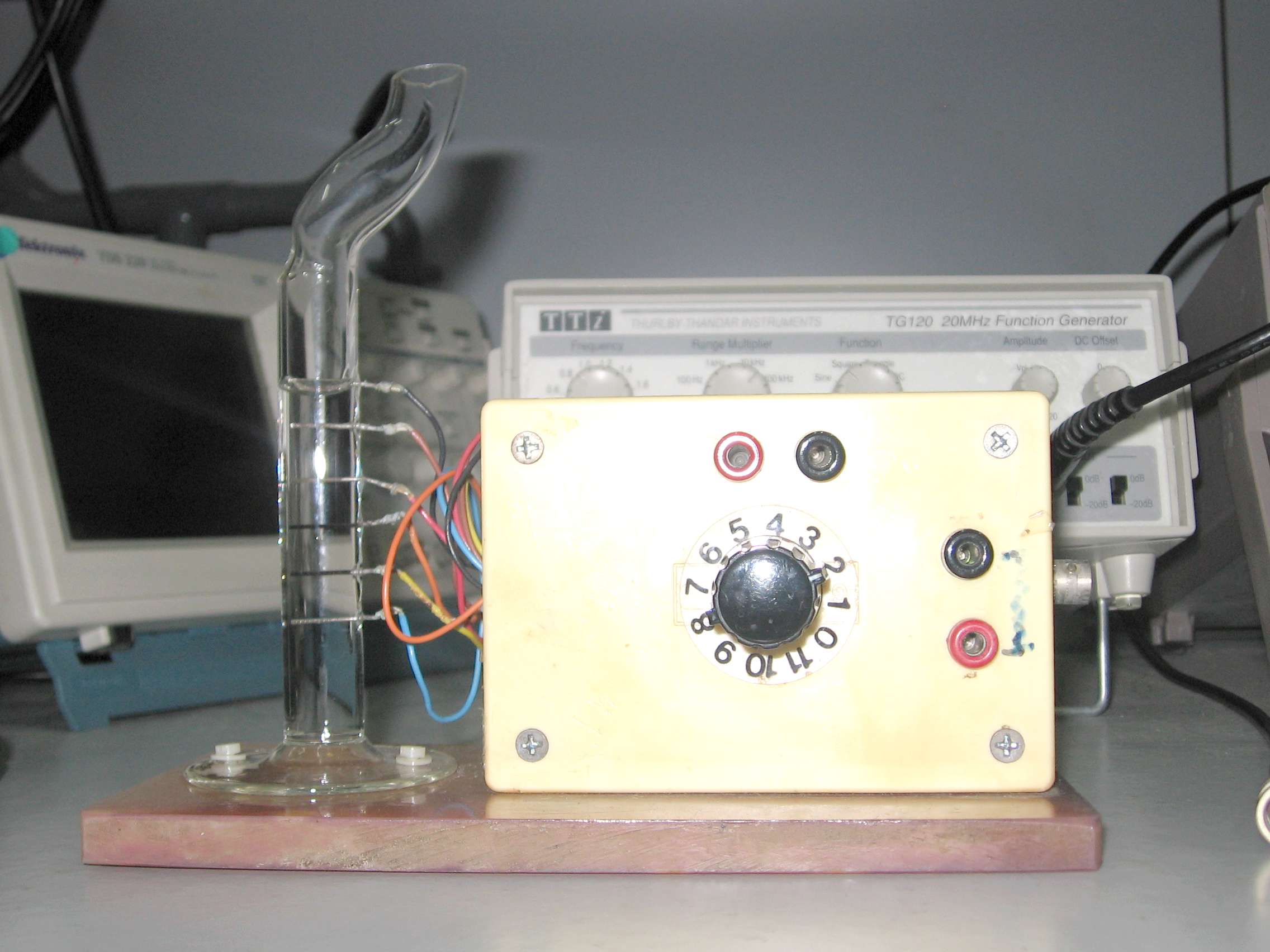
Figure 6 shows the 4-electrode cell experimental setup, which actually contains 6 electrodes. Different pairs of electrodes are connected in the "in" and "out" positions, according to the position of the knob. The following table shows which knob position connects which electrodes:
| Electrode No. | 1 | 2 | 3 | 4 | 5 | 6 |
| Position 1 | in | out | out | in | ||
| Position 2 | in | out | out | in | ||
| Position 3 | in | out | out | in |