Image Comparison

Image comparison of two images separated by a small distance (stereoscopic vision) or time (detection of movement) gives rich information about movement and depth.
Also image comparison may be used for recognition.
In comparing two images we need to know what point on one image corresponds to what point on the other image.
Contents |
[edit] Purpose
The purposes of this page is to demonstrate that creating a vision system is theoretically possible.
This page summarises the basic theory for creating a vision system.
[edit] Image Mapping Vectors
The array of vectors describe the relationship between the two images. The source point and the point it is mapped to should be similar in colour. Also the vectors should be similar to adjacent vectors.
The whole problem may be considered one of data compression. Inductive Inference tells us that the smallest (simplist) description of a problem is the most likely to be correct.
So if the source point and the destination point are similar in colour then little information is needed to describe the colour of one image in terms of the other.
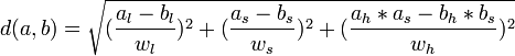
[edit] Colour Distance
A function is needed to measure the difference between one colour and another. Colour distance is described at,
However for the purpose of image comparison image brightness is very much determined by the angle and amount of incident light. So we should give less weight to lightness.
A simple model is,
Normalisation of colour over the whole picture may be useful in some circumstances.
[edit] Vector Distance
In compressing the vector data we can consider the vectors around the vector. We can use the average of the vectors as a predictor for our vector. The distance of the vector from the average of its neighbors is the vector distance.
[edit] Mapped colour
We choose a source point. Then we map it to the destination vector using the mapping vector. This doesnt give a pixel address in the image. Instead the colour at that point must be interpolated from the surrounding pixels.
[edit] Measure of Total Information
We sum the squares of weighted colour and vector distances over all points in the source image to give a total information distance. This information distance is related to the information content of the representation. We need to choose mapping vectors to minimise the information content (which is achieved by minimising the total image distance.
[edit] Interpreting Mapping Vectors
[edit] Complex Numbers
In describing the effects of rotation it is useful to use complex numbers to represent image position.
gives


now r represents rotation and scale.

for small  ,
,


By applying derivatives we get,

[edit] Rotation Matrix
I will borrow the formula for a rotation of angle  around an axis
  .
.
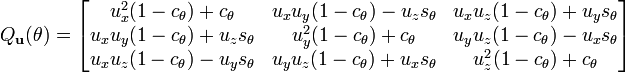
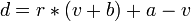
Now let us take a 3 dimensional point p. The position of the point after scaling and rotating is,
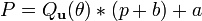
and after expanding (using Matrix Multiplication,


For a small angle θ use the approximation,
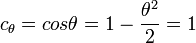
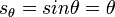
this gives,


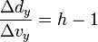
for stereoscopic vision, no rotation, just displacment in the x direction by the eye width.
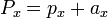


[edit] Projection onto View
A simplified formula for the projection of z on the image is,
 or
or 
 or
or 

and,
 or
or 
 or
or 
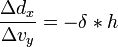
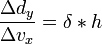
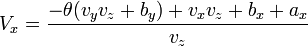
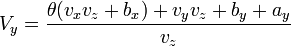
expanding this out to remove all refence to p gives,
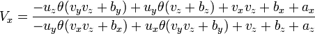
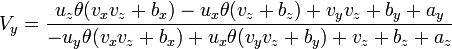
[edit] Rotate around Z
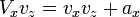
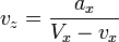
[edit] Eliminating vx


[edit] Stereoscopic Imaging
Displacement of two images by a distance in the x direction allows the derivation of depth information, which gives depth perception. X,Y rotation should not be seen in stereoscopic images.
for stereoscopic vision,

[edit] Recognition
Image comparison may be used for recognition. A stored image compared with a target image would give an array of mapping vectors.
These mapping vectors may then be analyzed for,
- Position
- Rotation
[edit] Object Model
Out of this modeling surfaces corresponding to objects may be identified, and recognised, leading to an object view of the world.
[edit] Conclusion
A numerical solution is needed to create the mapping vectors and to interpret the vectors to construct an object model.
There is a huge amount of processing required. Using multiple convential processors it should be possible to do this in real time.
A massively parrallel architecture like a neural network is better suited to this task.
But in theory it appears possible to construct a vision system that can perceive the world as objects. This is not the most biggest task to solve theoretically. It is more of an engineering problem.