3. COULOMETRIC
TITRATIONS
In a coulometric titration the titrant is generated electrochemically by constant current from a proper electrolyte. Coulometric titrations are in many ways similar to volumetric titrations: the concentration of the titrant is equivalent to the generating current, and the volume of the titrant is equivalent to the generating time. The two modes are exemplified with an argentometric titration (Fig.3-1).
Generating electrode: ![]()
Counter electrode: ![]()
![]()
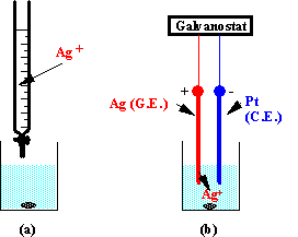
Fig.3-1 Titration of chlorides with Ag+: (a) volumetric, (b) coulometric.
Coulometric titrations have numerous advantages:
Coulometric vs Volumetric
Titrations
|
||
|
|
Coulometric
|
Volumetric
|
|
Preparation of standard solutions |
None |
Yes |
|
Standardization of titrant |
None |
Yes |
|
Storage of titrant |
None |
Yes |
|
Use of labile reagents |
Trivial |
Difficult |
|
|
Trivial |
Possible |
|
Dilution effects during titration |
None |
Yes |
|
Addition of microquantities of analyte |
Trivial |
Difficult |
|
Determination of microamounts of analyte |
Yes |
Difficult |
|
Determination of microvolumes |
Yes |
Difficult |
|
Accuracy of titration |
High |
O.K. |
|
Economy of reagent |
Maximal |
Depends |
|
Automation |
Perfect |
Possible |
|
Remote control |
Perfect |
Possible |
|
End-point detection |
Same for both modes |
|
|
Price |
Similar |
|
3.1.
Electrogeneration of titrant
The basic requirement of a coulometric titration is 100% current efficiency of titrant generation.
![]()
In the table below several options for electrogeneration of titrant are presented. The most straightforward options are those in which the titrant is produced as a result of (i) dissolution of electrode material or (ii) decomposition of the solvent at an inert electrode. The reagent precursor in those cases is present at infinitely large amounts.
Sources of electrogenerated titrant
|
||
|
Electrode material |
Solvent
|
Reagent precursor |
|
|
|
|
|
|
|
|
In a large number of coulometric titrations, however, the reagent precursor has finite concentration. For example, in order to generate bromine as titrant, bromide is added as precursor.
To ensure 100% current efficiency, the generation of titrant should be the only process, taking place at the generating (working) electrode. The current by which the titrant is generated has to be smaller than the limiting current of the electrode process of interest. If this condition is not maintained, some unwanted electrode process could take place and bring to the reduction of the current efficiency.
This will
be exemplified by a current-potential curve (Fig.3-2) obtained in stirred
solution containing
Note: For 100% current efficiency: ig
< il
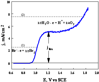
Fig.3-2 Experimental current-potential curve for oxidation of bromides at a rotating disk electrode.
Composition
of solution:
Area of the electrode: 0.16 cm2. Rotating rate: 400 rpm.
Auxiliary lines (1) and (2) are referred in the text.
3.2. Estimation
of the maximal generating current when reagent precursor is used
The amount of precursor reaching the electrode is determined by the rate of mass transport, which is controlled by the concentration of the precursor, the intensity of stirring and the cell geometry. Proper choice of those parameters is of paramount importance for ensuring 100% current efficiency. The rigorous mathematical analysis of mass transport in stirred solutions is a complex task. We shall proceed by a simplified approach, introduced by Nernst, using the concept of diffusion layer.
According to Nernst approach, a layer of thickness ![]() (the Nernst diffusion
layer), adjacent to the electrode, remains stagnant. Away from it the
solution is in motion and uniform in concentration. The thickness of the layer
remains unchanged with time. The mass transfer in the Nernst layer proceeds by
diffusion and the concentration gradient is linear. The model is rather
primitive, but adequate for a rough estimation.
(the Nernst diffusion
layer), adjacent to the electrode, remains stagnant. Away from it the
solution is in motion and uniform in concentration. The thickness of the layer
remains unchanged with time. The mass transfer in the Nernst layer proceeds by
diffusion and the concentration gradient is linear. The model is rather
primitive, but adequate for a rough estimation.
The concentration profile of the electroactive species in stirred solutions, according to the Nernst approach, is presented in Fig.3-3.
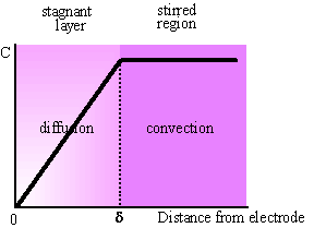
Fig. 3-3 Nernst model of mass transfer in stirred solutions.
The Nernst diffusion layer, ![]() , is:
, is:
·
independent
of time
·
inversely
dependent on square root of stirring rate
The flux of the electroactive species at the electrode surface is given by Fick's first law
 (1)
(1)
where C* and C(x=0) are the bulk and surface concentrations of the electroactive species and D is its diffusion coefficient. The corresponding current is
![]() (2)
(2)
A limiting value of the current, il, is reached at sufficiently large potentials, where C(x=0) = 0. Then
![]() (3)
(3)
The
thickness of the Nernst diffusion layer, ![]() , is inversely proportional to the square root of the
intensity of stirring. No exact analytical expression is available for a
bar-stirred solutions and
, is inversely proportional to the square root of the
intensity of stirring. No exact analytical expression is available for a
bar-stirred solutions and ![]() can be estimated only
experimentally by measuring il
at a given bulk concentration, C*, of electroactive
species. Furthermore,
can be estimated only
experimentally by measuring il
at a given bulk concentration, C*, of electroactive
species. Furthermore, ![]() is dependent on the
geometry of the cell, the electrode arrangement and the distance between the
bar and the electrode. Thus, we refer in our examples (Fig.3-2 and Fig.3-5) to
a rotating disk electrode, the current for which is independent of the above
mentioned geometric parameters. Analytical expression for il
at a rotating disk electrode has been derived.
is dependent on the
geometry of the cell, the electrode arrangement and the distance between the
bar and the electrode. Thus, we refer in our examples (Fig.3-2 and Fig.3-5) to
a rotating disk electrode, the current for which is independent of the above
mentioned geometric parameters. Analytical expression for il
at a rotating disk electrode has been derived.
![]() (4)
(4)
where ![]() is the rotating rate
in Hz, il in A, C* in mol/cm3,
is the rotating rate
in Hz, il in A, C* in mol/cm3, ![]() and D in cm2/s.
and D in cm2/s.

In titrimetric analysis bar-stirred solutions are used. Thus, equivalence in currents compared to rotating electrode is needed. Considering the cell presented in Fig.1-7 (cf., Titrimetric Methods of Analysis), effective stirring is achieved by rotating the magnetic stirrer in the range of 400 - 1200 rpm. (The upper value is limited by the appearance of vortexes, and the lower - ensures that the electrogenerated titrant has the chance to encounter virtually all the analyte within the time of about 100 s needed to reach the equivalence point in a continuous titration). The limiting currents obtained under these conditions are approximately equal to those observed when the electrode itself is rotated at the same rate.
3.3. Optimal values of generating current, concentration of precursor and area of working electrode
Plots of limiting current density, j = il /A, as function of concentration of precursor, calculated according to eq.4, are displayed in Fig.3-4.

Fig.3-4 Limiting current density in stirred solutions as function of concentration of precursor, calculated according to eq.4, for D = 10-5 cm2/s. The right axes corresponds to the recommended current density at the generating electrode for a coulometric titration.
Fig.3-4
provides an estimation of the limiting values of the current density at different
rotating rates. The generating current, as stated above, should be lower than
the limiting current of the precursor in order to ensure 100% current
efficiency. A safety factor of 2 is used in estimating the recommended current
density at a generating electrode in coulometric
titrations (right axes of Fig.3-4). Fig.3-4 can be used to determine the
concentration of reagent precursor for a given current density at the
generating electrode or vice versa. For example, if a titration is
carried out at 20 mA/cm2, for ![]() , the lowest concentration of the precursor that can be used
is ~60 mM. If the rate of rotation were decreased to
400 rpm, only 10 mA/cm2 could be passed at the same concentration
without affecting the current efficiency.
, the lowest concentration of the precursor that can be used
is ~60 mM. If the rate of rotation were decreased to
400 rpm, only 10 mA/cm2 could be passed at the same concentration
without affecting the current efficiency.
A well-designed experiment should ensure successful results also in less favorable conditions, thus the possibility of the working electrode being located in a region of reasonably low stirring rate (400 rpm) should be considered. The generating current, ig, in these conditions (Fig.3-4) is
![]() (5)
(5)
where n is the number of electrons involved in the electrogeneration of the titrant. (A different coefficient for eq.5 is given by Lingane1: 0.5 instead of 0.2. The difference may be related to differences in degree of stirring. Lingane refers to "well stirred solutions" and we refer to moderate stirring. Furthermore, we use a safety factor of 2).
Eq.5
provides a guide for determining the experimental parameters: area of generating
electrode and concentration of precursor. The generating current is chosen
considering the amount of analyte and a reasonable time for the titration to be
accomplished. For example, if the total amount of charge needed to reach the
equivalence point is 0.5 Coulomb and it is desired to accomplish the titration
in 100 s, a generating current of 5 mA is to be used.
The product Cprec (mM)·Ag
(cm2) should be at least 25 (cf., eq.5, with n = 1). Thus, for a
reasonable value of the area ranging from 0.5 to 2 cm2, the
respective concentration of precursor should be 50 to
3.4. Counter
electrode
In many cases the reaction at the counter electrode is not compatible with the reaction of interest. There are several reasons for incompatibility:
![]() The product of the reaction between the
analyte and titrant is restored at the counter
electrode to the initial form of the analyte, e.g., titration of Fe2+
with Ce3+ as precursor. Fe3+, the
product of the titration, is reduced to Fe2+ at a non-isolated Pt
counter electrode.
The product of the reaction between the
analyte and titrant is restored at the counter
electrode to the initial form of the analyte, e.g., titration of Fe2+
with Ce3+ as precursor. Fe3+, the
product of the titration, is reduced to Fe2+ at a non-isolated Pt
counter electrode.
![]() The electrogenerated
titrant reacts at the counter electrode, e.g., titration
of Cl- with electrogenerated
Ag+. Silver ions, which did not have the chance to react
with Cl-, are lost by being reduced at the
counter electrode.
The electrogenerated
titrant reacts at the counter electrode, e.g., titration
of Cl- with electrogenerated
Ag+. Silver ions, which did not have the chance to react
with Cl-, are lost by being reduced at the
counter electrode.
![]() The main product at the counter
electrode reacts with the analyte or with the electrogenerated
titrant, e.g., titration of H+ with electrogenerated
The main product at the counter
electrode reacts with the analyte or with the electrogenerated
titrant, e.g., titration of H+ with electrogenerated
An accepted solution for all these problems is isolation of the counter electrode. This, however, imposes experimental difficulties:
(i) the solution of the counter compartment has to be replaced frequently;
(ii) incomplete isolation of the counter electrode will affect the accuracy of the titration;
(iii) it is unsuitable for automation and miniaturization; (iv) it substantially increases the resistance between the electrodes.
Thus, it is preferable to use a non-isolated counter electrode. Care must, however, be taken to ensure 100% current efficiency.
Note: If the resistance between the generating and the counter
electrodes reaches ![]() , the passed current is limited to 50 mA,
since most coulometers operate under 40 V.
, the passed current is limited to 50 mA,
since most coulometers operate under 40 V.
3.5. Models for
non-isolated counter electrodes
There are several approaches in devising non-isolated counter electrodes.
(a) Creating
conditions at which an undesired process is prevented by limiting the potential
of the counter electrode.
The Ag/AgBr
counter anode2,3 is an elegant solution for the titration of
H+, where in a two-platinum electrode cell the
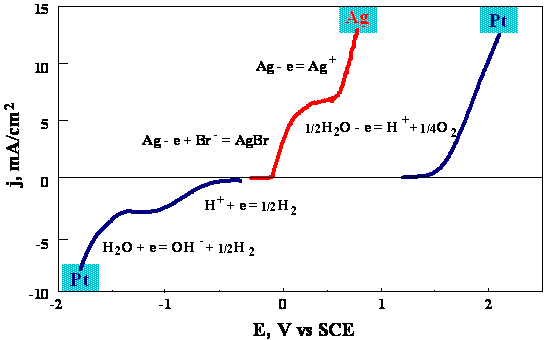
Fig.3-5 Current-potential relationship at rotating disk electrodes (platinum and silver) at 400 rpm.
At
Pt-RDE:
At
Ag-RDE:
The composition of the solution is modified by adding excess of a halide salt, whose role is forming insoluble silver salt, thus preventing reduction of Ag+ at the cathode. (Reduction of Ag+ would reduce the titration efficiency).
The excess
of X- has to be controlled due to the formation of soluble complexes
AgX2- ,AgX32- ,AgX43-.
The total concentration of the dissolved species as function of concentration
of halide is given in Fig.3-
(b) Hampering
direct reaction of the titrant at the counter
electrode based on geometric and kinetic considerations.
One of the problems resulting from the use of non-isolated counter electrodes is that the electrogenerated titrant can react at it instead of reacting with the analyte. A general solution is presented here4. The basic principle is to render mass transport of the titrant at the counter electrode negligibly small by modifying the factors involved. Consider for this purpose the Nernst approach, which allows us to estimate the mass transport limited current in stirred solutions (eq.3).
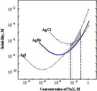
Fig.3-6 Solubility of silver halides in sodium halide solution at 18oC (K.H.Leiser, Z. Anorg.Allgem. Chem., 292, 97 (1957)).
Simple analysis of the equation shows the parameters, which need to be modified:
![]() Decreasing the area
of the counter electrode.
Decreasing the area
of the counter electrode.
![]() Using an electrode geometry for which il will be
minimal.
Using an electrode geometry for which il will be
minimal.
![]() Keeping the Nernst
diffusion layer
Keeping the Nernst
diffusion layer ![]() as large as possible.
as large as possible.
![]() Keeping the
concentration of the titrant in the solution as low
as possible.
Keeping the
concentration of the titrant in the solution as low
as possible.
Each of the above points is treated below.
Decreasing the area. For the case where the main reaction at the counter electrode is the decomposition of the solvent, a high current density of up to at least 100 mA/cm2 can be used. Thus, if a current of 10 mA is used in the coulometric titration, a counter electrode as small as 0.05 cm2 can be employed.
Geometry of the counter electrode. A small disk is better than a thin wire of identical area, since the flux at the former is smaller.
Keeping ![]() as large as possible. The only way to increase the
Nernst diffusion layer
as large as possible. The only way to increase the
Nernst diffusion layer ![]() at the counter electrode
is to decrease the stirring rate in the vicinity of the counter electrode. This
is somewhat contradictory to the requirement of efficient stirring. However, if
a small cell with a volume of 5 - 10 ml is used (Fig.1-7), efficient stirring
throughout the solution can be reached at moderate rotation of the magnetic bar
(400 - 600 rpm). The optimal place to locate the counter is far away from the
working electrode and from the magnetic stirrer.
at the counter electrode
is to decrease the stirring rate in the vicinity of the counter electrode. This
is somewhat contradictory to the requirement of efficient stirring. However, if
a small cell with a volume of 5 - 10 ml is used (Fig.1-7), efficient stirring
throughout the solution can be reached at moderate rotation of the magnetic bar
(400 - 600 rpm). The optimal place to locate the counter is far away from the
working electrode and from the magnetic stirrer.
Low
values of the instantaneous concentration of electrogenerated
titrant in the solution can be achieved by:
(i) Producing a uniformly distributed titrant by efficient stirring and using a large-area
generating electrode.
(ii) Increasing the
rate of reaction between the analyte and the electrogenerated
titrant. The higher the rate, the smaller the
concentration of free reagent, and thus the smaller the chances for its
reaction at the counter electrode. For example, the rate of reaction between
chloride and Hg(I) can be substantially changed by manipulating the composition
of the solution. Acidity and alcohol content are the most important factors.
For the completion to 90% of the reaction between Cl-
and Hg(I) (mixing
The above
outlined principles will be tested with an example of constant-current
titration of Cl- with electrogenerated
Hg(I). A
![]()
The current of the electroreduction of Hg(I) can be
estimated according to Levich equation (eq.4),
provided the instantaneous concentration of Hg(I) is known. It is, however,
very difficult to determine the instantaneous concentration. A worst case, in
which none of the titrant reacts up to the
equivalence point, will be considered. Since the generating current is
constant, the instantaneous concentration of Hg(I) increases linearly with
time, and its average concentration up to the end point is half the initial
concentration of the analyte, i.e., ![]() . This represents 0.2% of the total current passed, leading
to a 0.2% error at most. In fact the error is much smaller since the basic
requirement for a titration is a fast reaction between titrant
and analyte.
. This represents 0.2% of the total current passed, leading
to a 0.2% error at most. In fact the error is much smaller since the basic
requirement for a titration is a fast reaction between titrant
and analyte.
Note: (1)
Conditions for titration with ![]() :
:
·
strong
acid (HClO4 or HNO3)
·
![]()
(2) Electrode reduction of ![]() at the counter
electrode decreases the efficiency of the titration.
at the counter
electrode decreases the efficiency of the titration.
Reaction of interest: ![]()
Competing reaction: ![]()
An additional example of successful application of the above principles is the titration of As(III) with electrogenerated iodine. The reaction between iodine and As(III) is very fast. Thus, even with less strict observation of the above mentioned conditions, high accuracy can be achieved with a non-isolated counter electrode.
In conclusion, the approach proposed above is a simple and elegant method for using a non-isolated counter electrodes for cases in which the electrogenerated titrant can react at the counter electrode. The flux of the titrant at the counter electrode is rendered virtually zero on the basis of geometric and kinetic considerations. Another benefit of this approach is that it also largely decreases the possibility that the analyte or its product would react at the counter electrode.
As good
analytical practice, however, it is suggested to test whether the functioning
of the non-isolated counter electrode meets all expectations. The example given
below (titration of Cl-) demonstrates a
problem encountered with a non-isolated counter electrode. The titration of Cl- can be performed with electrogenerated
Ag+ or with ![]() . The difference between the two titrants is that silver, which may be deposited on the
non-isolated counter electrode, forms dendrites, while mercury being a liquid
metal, does not. After certain incubation period, typically 300 s, at a
generating current of 2 mA, the silver dendrites
start to protrude toward the solution and form a barely visible web with
considerable area. Thus, the central condition of a small-area counter is
violated in the case of silver, and from that point spongy black silver
deposits start flowing in the solution and large and irreproducible delays of
the end point are observed.
. The difference between the two titrants is that silver, which may be deposited on the
non-isolated counter electrode, forms dendrites, while mercury being a liquid
metal, does not. After certain incubation period, typically 300 s, at a
generating current of 2 mA, the silver dendrites
start to protrude toward the solution and form a barely visible web with
considerable area. Thus, the central condition of a small-area counter is
violated in the case of silver, and from that point spongy black silver
deposits start flowing in the solution and large and irreproducible delays of
the end point are observed.
Limitations of the proposed counter electrodes. The principles outlined above are suitable for most types of titrations, with few exceptions. For example, titrations at which the products formed at the counter electrode react with the analyte (in the titration of OH- with non-isolated counter electrode, H+ formed at the generating electrode is counterbalanced by OH- formed at the counter electrode).
3.6. Isolated
counter electrodes. Design and materials
Isolation between the counter and generating electrodes is achieved by several ways:
1. The electrodes are placed in separate vessels joined by an electrolyte bridge, closed at both ends by porous membrane (sintered glass or ion-exchange membrane).
2. The counter electrode may be kept in a single armed bridge with a fine porous membrane, isolating it from the solution being titrated. In this case there may be some diffusion from the counter electrode compartment, and thus it is advisable to complete the titration quickly.
3. In place of a porous membrane, a plugged tube
of Vicor brand thirsty glass (Corning
7930) effectively prevents mixing of the two solutions while maintaining
electrolyte contact. Thirsty glass is a porous, adsorbent glass with 28% of
volume void and 4 ![]() m average pore diameter. Thin tubes (inner diameter ~3.5 mm
and wall thickness ~1 mm) are recommended for
m average pore diameter. Thin tubes (inner diameter ~3.5 mm
and wall thickness ~1 mm) are recommended for ![]() . The bottom end of the tube is sealed with a small soft plug
(silicon rubber, viton or others).
. The bottom end of the tube is sealed with a small soft plug
(silicon rubber, viton or others).
The electrolytic resistance between the counter and the generating electrode, Rc-g, is considerably increased by the separator. Thirsty glass tubes are the best separators in view of low resistivity and effective separation between generating and counter compartments.
The
electrolytic resistance Rc-g is
easily measured by a conductometer connected to the
counter and working electrodes. The product iRc-g
can reach considerably large
values. With a sinter separator, Rc-g
may be as high as 500 ![]() ; at ig =20 mA, the product iRc-g
alone reaches 10 V. The overall potential across the cell, Vc-g,
is mainly determined by the potential drop iRc-g.
It should be noted, that due to safety considerations the galvanostats
for coulometric titrations are usually constructed
with limitation of the output potential. The output voltage of a galvanostat, Vc-g,
for coulometric titrations is limited to ~40 V.
; at ig =20 mA, the product iRc-g
alone reaches 10 V. The overall potential across the cell, Vc-g,
is mainly determined by the potential drop iRc-g.
It should be noted, that due to safety considerations the galvanostats
for coulometric titrations are usually constructed
with limitation of the output potential. The output voltage of a galvanostat, Vc-g,
for coulometric titrations is limited to ~40 V.
Several electrode materials are suitable as isolated counter electrode: Pt, Au, C, Ag, W (tungsten only as cathode), etc. The area of the counter electrode may be smaller than that of the working electrode (Ac > 0.1 Ag).
3.7. Working
electrodes. Materials and shapes
The choice of material for the generating electrode is made according to the electrode reaction in which the titrant is generated:
Typical Electrogenerated Titrants
|
|||
|
|
Electrogenerated titrant |
Generating electrode |
Reagent precursor |
|
Oxidants |
Br2 |
Pt |
Br- |
|
I2 |
Pt |
I- |
|
|
Cl2 |
Pt |
Cl- |
|
|
Reductants |
Fe(II) |
Pt |
Fe(III) |
|
Cu(I) |
Pt |
Cu(II) |
|
|
Sn(II) |
Au |
Sn(IV) |
|
|
U(V), (IV) |
Pt |
UO2SO4 |
|
|
Precipitation and complexation
agents |
Ag(I) |
Ag |
Ag |
|
Hg(I) |
Hg(Ag) |
Hg |
|
|
EDTA |
Hg(Ag) |
Hg-EDTA2- |
|
|
Acids and bases |
OH- |
Pt |
H2O |
|
H+ |
Pt |
H2O |
|
Inert electrodes, mainly Pt or Au, are used in redox reactions involving soluble species.
Active electrode as Ag and Hg are used for the generation of Ag(I) and Hg(I).
Except for mercury, all other electrodes are convenient and safe for use. Mercury pool electrodes are commonly mentioned in the literature, but unless special precautions are taken, they are unsafe. Mercury-coated gold electrodes have been proposed as substitute. The problem is the fast disintegration of the gold. We recommend the use of mercury-coated silver electrodes, which can be used over years.
The shape
of the electrode is dictated by the price of the metal. Because of its
relatively low price, silver may be used as rods (2 or
3.8. Supporting
electrolyte
The prime task of the supporting electrolyte is to reduce the resistance between the generating and counter electrodes so that the voltage between them is within the dynamic range of the galvanostat. Most instruments designed for coulometric titrations operate up to 40 V. If this limit is exceeded, the following measures can be taken: (i) increasing the concentration of the supporting electrolyte, (ii) decreasing the resistance of the diaphragm separating the counter electrode compartment or (iii) decreasing the current.
While in a large group of titrations any inert electrolyte can be used, there are several cases in which both the type and the concentration of electrolyte play a role in the chemistry of the system. Several examples will be given.
Electrogenerated Ce(IV). The electrogeneration of strong oxidants (Ce(IV), Cl2) poses a problem due to competing reactions. The stronger the oxidant, the higher the potential of the generating electrode during the electrogeneration of the oxidant. For very strong oxidants the electrode surface of even noble metals becomes covered with oxides:
![]()
and at more positive potentials oxygen is evolved due to electrooxidation of water:
![]()
High current efficiency is achieved by:
![]() shifting the water
decomposition to more positive potentials by increasing the proton
concentration;
shifting the water
decomposition to more positive potentials by increasing the proton
concentration;
![]() shifting the potential of the reaction
of interest to more negative potentials by (i)
increasing the concentration of the precursor: for a given current density, the
higher the concentration of the precursor, the more negative the potential of
its electrooxidation; (ii) addition of complexant that stabilizes the titrant
in respect to its precursor.
shifting the potential of the reaction
of interest to more negative potentials by (i)
increasing the concentration of the precursor: for a given current density, the
higher the concentration of the precursor, the more negative the potential of
its electrooxidation; (ii) addition of complexant that stabilizes the titrant
in respect to its precursor.
The electrogeneration of Ce(IV) was
thoroughly studied by Lingane1 (see figures below). The
current-potential curves for oxidation of Ce(III) in
different acid solutions are given in the left figure. The plots for the
background due to oxide formation and oxygen evolution are also included. The
main difference between the two acids is in the negative shift of the potential
for the generation of Ce(IV). In H2SO4
the negative potential shift results from the complexation
of Ce(IV)
with ![]() . The effect of the acids on the background currents is elatively small.
. The effect of the acids on the background currents is elatively small.
The values of ![]() are given in the table
below:
are given in the table
below:
|
Acid |
|
|
|
1.44 |
|
|
1.70 |
The respective current efficiencies are shown in the right figure.
A current efficiency of 99.8% is achieved under the following conditions: a)
sulfuric acid (
|
Current-potential plots for oxidation of Ce3+ and the respective plots for the oxidation of water at a Pt electrode. |
Current efficiency for electrogeneration of Ce4+ as a function of current density and solution composition. |
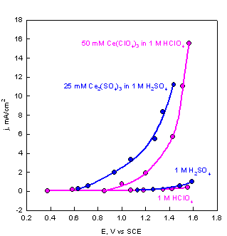
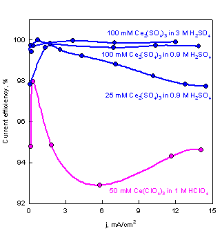
Optimal conditions for
generation of Ce(IV):
·
Presence
of 2-
·
Precursor
·
Current
density 1-10 mA/cm2
A relatively narrow range of optimal current density characterizes the electrogeneration of strong oxidants. Beyond the upper limit there will be a competition from the oxidation of water, and below the lower limit a formation of platinum oxide interferes.
Non-isolated Ag anode in a solution of halides
(counter electrode in titration of H+). Such an electrode is
described in this chapter, section 3.5. The role of the halide is the formation
of an insoluble silver salt. However, in excess of halide, soluble complexes
are formed. In the concentration range of interest, 5-
Titration of Cl-
with electrogenerated Hg22+.
The presence of strong acid is essential for the precipitation reaction to
proceed in reasonable rate. The minimal concentration is
3.9. Cells
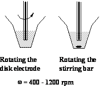
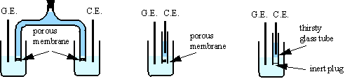
A great variety of cells and electrode arrangements are found in the literature. Volumes in the range of 0.1 to 200 ml are used. The cell recommended here with different generating electrodes is shown in Fig.3-7. The working volume in the lower part of the cell is 3 to 10 ml.
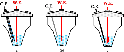
Fig.3-7 Cells and electrodes in coulometric titrations:
(a) with an isolated counter electrode;
(b) with a non-isolated small-area counter electrode, designed to hamper direct reaction of the titrant at it;
(c) with a non-isolated counter electrode at which only inactive products are formed.
3.10. Collecting
data
Coulometric titrations take little time and you are advised to repeat each one at least five times and carry out a statistical analysis on the results. For each experiment report mean, standard deviation and reject data according to rules and common sense.
SUMMARY OF COULOMETRIC TITRATIONS
![]()
Exp.1. Titration of As(III)
Chemicals 1.
2.
3. Combined
4. 1% starch solution (freshly prepared)
5.
Electrodes: generating - Platinum;
counter - Non-isolated platinum, carbon or tungsten (area 0.03 - 0.1 cm2);
indicating - Twin platinum electrodes.
Electrode reactions:
anode: ![]() (I2 in excess of I- is in the form of I-3
)
(I2 in excess of I- is in the form of I-3
)
cathode: ![]() (before the end point)
(before the end point)
![]() (after
the end point)
(after
the end point)
The titration of As(III) is based on the reaction:
![]()
The optimal pH range for performing the reaction is 7 -
9. Complete oxidation of As(III) requires pH above 7, but to avoid disproportionation of iodine the pH must be smaller than 9.
The bicarbonate used in this experiment has the ability to restrict the pH in
this range (Explain! Hint: cf. Exp.
Note: Disproportionation
of I2 at pH > 9:
![]()
![]()
Procedure
a) Visual
detection of the end point
Insert the electrodes into the cell and connect them to the coulometer. Note that the auxiliary electrode is not isolated. Why I2 is not reduced at the cathode prior to the end point?
Add to the titration vessel just enough KI-NaHCO3 solution to cover the electrodes and 2 drops of 1% starch solution. Adjust the current to 20 mA. The clock should be zeroed at the beginning of each titration.
Pretitration. Start the stirrer. Turn on the current for a short time (~1 s) and note the darkening of the solution. Add a small amount of the arsenite stock solution dropwise until the color disappears. Then operate the current on-off switch intermittently until a light blue color develops in the entire solution. This color will be taken as the end point of the titration. Set the timer back to zero.
Pipet 0.500 ml of the
As the end point is approached, the titration should be stopped periodically to allow the iodine (seen as blue streaks emanating from the generating electrode) to react before addition of the next portion of the titrant. At this stage the current should be stopped for short periods of time (~0.1 s).
Return the timer to zero, pipet another 0.500 ml of the sample into the vessel and repeat the coulometric titration. Several runs may be made in the same solution. Repeat until at least three consecutive values agree to within ± 0.2 s.
Dilute your unknown arsenite sample in the volumetric flask to the mark and titrate 0.500 ml portions of it as you did before.
b) Potentiometric determination of the end point
In the above experiment you performed your first coulometric titration. You observed the generation of the titrant (I2 formation) and determined the end point with reasonable accuracy and relative ease. In this part of the experiment you will repeat the above titration, but with an arsenite solution ten times more diluted. What accuracy would you expect to obtain in this case using the visual end-point determination?
Try
to envisage what effort would be required to perform the same titration in its
volumetric version: preparation of titrant solution,
its standardization and storage, use of clean glassware, pipettes, burettes,
analytical balances, chemical standards and others.
Two improvements are introduced in this section:
(i) The titration is performed with monotonic generation of titrant, using the repetitive mode of titrations (Titrimetric Methods of Analysis, section 1.5);
(ii) The end point is determined potentiometrically
using two identical platinum electrodes. Since the titration is performed in a
continuous mode, well-defined end point is observed without passing current
between the twin indicating electrodes (note, that for point-by-point titration
a small constant current (~1 ![]() A/cm2) should be passed between the indicating
electrodes).
A/cm2) should be passed between the indicating
electrodes).
Repetitive-monotonic
titration. Add to the titration vessel just enough KI - NaHCO3
solution to cover the electrodes. Pipet 0.500 ml of
the ![]() A. Titrate until the expected potential peak is observed.
Stop the titration somewhere after the end point, add to the cell an additional
0.500 ml portion of the sample and continue to titrate. Perform a series of
repetitive titrations in the same solution. The time elapsed from peak to peak
is the time corresponding to the end point and does not include the time lag of
the electrodes.
A. Titrate until the expected potential peak is observed.
Stop the titration somewhere after the end point, add to the cell an additional
0.500 ml portion of the sample and continue to titrate. Perform a series of
repetitive titrations in the same solution. The time elapsed from peak to peak
is the time corresponding to the end point and does not include the time lag of
the electrodes.
Perform an additional series of titrations under the above conditions, but without passing current between the indicating electrodes. Compare the two types of titrations and comment.
Measure the distances between the end points and calculate the average time and the standard deviation. Compare the average with the time of the first titration.
Report the concentration of As(III) in mol/l:
a) in the stock solutions (note that the stock solutions are not standardized),
b) in the unknown,
as received in the volumetric flask.
Exp.2. Acid-base titrations
Chemicals 1.
2.
3.
4. 0.1% Bromothymol Blue or Methyl Red solution
Procedure (a)
Electrodes: generating - Platinum (~0.3 cm2 area);
counter (isolated) - Platinum, tungsten (only as cathode) or carbon.
Electrode reactions
cathode: ![]()
anode:
![]()
Pretitration. Add to the coulometric
cell few drops of
Pipet 1.00 ml of
A sample can also be pretitrated by simply reversing the polarity of the electrodes and passing the same current for the same length of time. The composition of the solution is now the same as it was before the start of the first titration. Now reverse the polarity once again and titrate.
Procedure (b)
Electrodes: generating - Platinum;
counter (non-isolated) - Silver (~1.5 mm wire).
Electrode reactions
cathode: ![]()
anode: Ag + Br- = AgBr + e
Acids can be titrated with a non-isolated silver counter electrode in presence of KBr as background electrolyte. In this case the anodic reaction is the formation of AgBr, which adheres to the electrode and there is no need to isolate the counter electrode. The bromide deposit should be mechanically removed from time to time.
Replace
the isolated platinum electrode with a silver electrode. Add just enough of
Report the normality of the acid as obtained by the two sets of electrodes.
Questions
1. With the help of current-voltage curves, describe the reactions taking place at the working electrodes, at various stages of the titration. What are the reactions at the counter electrode?
2. Why is it necessary to separate the electrode in one case and not in the other?
3. Could the generating and counter electrodes be replaced by graphite instead of platinum? Explain.
4. Is a reagent precursor necessary in acid-base reactions? Explain.
5. Describe an experimental method for a base titration. Is it possible in this case to use platinum and silver as the generating electrode pair?
6. What is the
advantage of coulometric generation of
7. Suggest a coulometric apparatus for the titration of a) dichromate, b) bromide.
8. Why is it not
convenient to titrate coulometrically large volumes
of more concentrated solutions (e.g., 100 ml of
Exp. 3. Determination of chlorides in drinking water with coulometrically generated mercurous ion
Chemicals 1. Methanol
2.
3.
Electrodes: generating - Mercury-coated silver electrode;
counter - Non-isolated platinum or tungsten electrode (area ~0.05 cm2);
indicating - Twin mercury-coated silver electrodes.
Electrode reactions:
Anode: ![]()
![]()
The mercurous ion (![]() ) is the main product. However, the possible formation of
small amounts of Hg2+ does not affect the accuracy of the titration,
since in both cases one electron per one chloride anion is involved.
) is the main product. However, the possible formation of
small amounts of Hg2+ does not affect the accuracy of the titration,
since in both cases one electron per one chloride anion is involved.
Cathode: ![]()
At low
concentration of chlorides (lower than
The
solubility of Hg2Cl2 is several orders of magnitude lower
in 70-80% methyl alcohol (Fig.3-8) and mercury ions can be generated at 100%
efficiency from a mercury-coated silver anode. The end point is determined potentiometrically with two identical mercury-coated silver
electrodes at constant current of 0.5 ![]() A (~2
A (~2 ![]() A/cm2).
A/cm2).

Fig.3-8 Apparent solubility product (left axis) and
solubility (right axis) of Hg2X2 as function of
percentage of methanol (data taken from E.P.Przybylowicz
and L.B. Rogers, Anal.Chem., 28, 799
(1956)).
Procedure
The titration is performed in the repetitive-monotonic mode (Titrimetric Methods of Analysis, section 1.5).
1. Set the current
for generating Hg(I) to 2 mA and the current for the
indicating electrodes to 0.5 ![]() A.
A.
2. Add to the coulometric cell a 0.500 ml sample of tap water or chloride
solution, about 0.2 ml (5 drops) of
3. Start to titrate. Continue the titration until the expected potential peak is observed. Stop the process at any point after the peak of the end point.
4. Add an additional 0.500 ml portion of the sample to the previously titrated solution. Continue to titrate. Make several more additions of the sample. Observe the titration curve. The time elapsed from peak to peak is the time corresponding to the end point and does not include the time lag of the electrodes.
5. Measure the distances between the peaks and calculate the average time and the standard deviation. Compare the average with the time of the first titration. Report the concentration of Cl- in ppm and in mol/l.
Exp. 4.
Titration of Br- or I- with generation of Ag+
Chemicals 1.
2.
3.
4. 0.3% PVA (Polyvinyl alcohol)
Electrodes: generating - Silver and platinum electrodes;
indicating - Twin silver wires.
Procedure
Add to the
coulometric cell 0.500 ml of
Note: PVA is a surfactant.
It hampers the coating of the generating anode with AgX.
Carry out a titration at a generating current of 2 mA. Use the repetitive-monotonic method as described in Titrimetric Methods of Analysis, section 1.5.
The silver generating electrode gradually acquires a coating of silver halide, which isolates electrically the electrode and should be removed mechanically from time to time. Clean the silver wire with a fine grade emery paper and rinse it with distilled water. At the end of the experiment clean the electrode and store it in the vessel provided.
Report the concentration of the halide in mol/l.
Questions
1. With the help of current-voltage diagrams list the reactions, which take place at the silver generating electrode at various stages of the titration.
2. In the titrations carried out in this experiment the electrode itself took part in the reaction. Is the addition of a precursor necessary in such a case?
3. Why the counter electrode may not be isolated?
4. What is the purpose of the KNO3?
5. Is this type of automatic titration possible in the case of an acid-base titration with a glass electrode? Why?
Exp. 5. Titration
of Fe2+ with coulometrically generated Ce4+.
Amperometric
indication of the end point
Principle
of the method. The potentiometric indication for
the titration of Fe2+ with Ce4+ is not applicable at low
concentration levels (<
In order to avoid the formation of oxides we propose an amperometric type of indication, where the indicating electrode is kept at a constant potential, negative to the potential at which oxides are formed5.
Concentrations of Fe2+ as low as 20 ![]() M can be determined in continuous titrations with a precision
of 2%.
M can be determined in continuous titrations with a precision
of 2%.
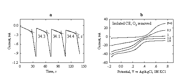
Fig.3-9 (a) Repetitive coulometric
titration of
Initial
composition: 200 ![]() L
L
(b) Voltammograms at different stages of the titration (progress of titration F = 0 – 1.4) of Fe2+ at a Pt-RDE (0.16 cm2 area).
Rotation
rate: 400 rpm. Initial composition:
Chemicals 1.
2.
Electrodes: Generating - Platinum anode (area 0.2 - 1 cm2) and non-isolated cathode (Pt, C, W or Au; ~0.05 cm2);
Indicating - Platinum wire (area ~0.2 cm2) and reference electrode.
Electrode reactions
anode: ![]()
![]()
cathode: ![]()
Overall reaction during titration: ![]()
Procedure
The progress of the titration is followed by amperometric indication. A constant potential of +420 mV vs Ag/AgCl/1 M KCl is applied to the indicating electrodes. The current, flowing in the indicating system, is recorded.
Add to the
coulometric cell about 4 ml of
Use the repetitive mode to perform a series of titrations. In order to avoid the oxidation of Fe2+, the time of the interruption between subsequent titrations is to be kept short (not more then few seconds). It is adviced to add the new portion of analyte without interrupting the titration.
Treatment of results
1. Calculate the concentration of Fe2+ in the solution.
2. With the help of current-voltage diagrams, list the reactions that take place at the working generating electrode at various stages of the titration.
3. What is the role of Ce3+?
Exp. 6. Determination of ascorbic acid in a Vitamin C tablets
The titration is based on the following reaction:
Ascorbic acid + Br2 + H2O = Dehydroascorbic acid + 2Br- + 2H+
Chemicals 1. Vitamin C tablets
2.
Electrodes: generating - Platinum;
counter
- Isolated platinum wire or graphite in
indicating - Twin gold electrodes (area 0.2 - 0.3 cm2).
Procedure
The
bromine is coulometrically generated at a platinum
electrode and the end point of the titration is followed potentiometrically
by passing a small current of about 0.5 ![]() A between the indicating electrodes.
A between the indicating electrodes.
You are
provided with a Vitamin C powder, obtained from about 10 Vitamin C tablets.
Dissolve in water 50 mg of the powder in a 250 ml measuring flask, make up to
volume. The resulting solution is somewhat cloudy due to the presence of inert
substance in the tablets. Transfer 0.500 ml of the Vitamin C solution to the coulometric cell, add about 5 ml of
Use the repetitive mode of titration. Report % of ascorbic acid in the tablet.
Note: Keep the Vitamin
C solution out of light and perform the titration within two hours after the
preparation of the solution.
References
1. J. J. Lingane, Electroanalytical Chemistry, Interscience Pub., 1958.
2. L. Szebelledy and Z. Somogoi, Z. Anal.
Chem., 112, 395(1938).
3. J. J. Lingane, Anal. Chim. Acta, 11, 283(1954).
4. E. Kirowa-Eisner, D. Tzur and V. Dosortzev, Anal. Chim. Acta, 359, 115(1998).
5. D. Tzur, V. Dozortsev and E. Kirowa-Eisner, Anal. Chim. Acta, 392, 307(1999).
Recommended
Literature
1. D. A. Skoog, Principles of Instrumental Analysis.
2. D. A. Skoog and D. M. West, Principles of Instrumental Analysis.
3. D. A. Skoog and J. J. Leary, Instrumental Analysis.
4. L. Meites and H. C. Thomas, Advanced Analytical Chemistry,
ch.7-11.
Go to Main Page