4. CONDUCTOMETRIC TITRATIONS
Exp. 1. Determination of sulfates in drinking water
4.1. The chemistry of the system
A
large number of the analytical methods for determination of sulfates are based
on precipitation of BaSO4 or PbSO4. Gravimetric, turbidimetric
and various titrimetric techniques have been used.
The
determination of the sulfates in drinking water is based on a conductometric
titration, where sulfates are precipitated as BaSO4
![]()
The
precipitation process has been the subject of comprehensive studies. In respect
to a conductometric titration of sulfates in drinking water, the following
interferences have to be considered:
(i) coprecipitation of Ca2+ and
Mg2+;
(ii) precipitation of bicarbonates and
carbonates as BaCO3;
(iii) H+ interferes if the
indifferent anion of the titrant (Ba2+) is a weak acid.
To
overcome the interferences, an efficient pretreatment performed in an
ion-exchange flow system is used1.
The strategy
of the experiment in view of the above points:
1.
The interference of Ca2+ and other cations is overcome by replacing
them with another cationic species via a cation exchange resin. Desirable
cations are Li+ or Na+, however an intermediate step -
replacement to H+ - is taken in order to discard carbonates and
bicarbonates.
2.
As a result of the above step, the carbonates and the bicarbonates are
transformed to carbonic acid. Carbonic acid can be purged by i) boiling the
solution, ii) saturating the solution with a gas different than CO2.
A different, recently developed approach, based on thin-film gassing out, which
is both efficient and well adapted to flow processes, has been used.
3.
After discarding the interfering cations and anions, the solution contains
protons and the anions originally present in the sample, except for the
carbonic species. The protons are neutralized in order to enable the usage of
the titrant containing acetate as counter anion and also in order to reduce the
background conductance. The neutralization is normally carried out with a
pH-metric titration. In this experiment a different, more efficient and
well-adapted approach for a flow process is used: the protons are exchanged via
a cation exchanger to Li+ or Na+ ions.
4.2. Factors of importance in a
precipitation conductometric titration
·
In order to
obtain a sharp-angled conductometric titration curve it is advantageous to use
a titrant whose indifferent (counter) ion has a relatively low ionic
conductance (Fig.4-1). By consulting Table 1 the counter anion of the titrant
is chosen to be acetate.
Table 1. Equivalent Conductivity at Infinite Dilution at 250C
|
Cation |
|
Anion |
|
|
H+ |
350 |
OH- |
198 |
|
Li+ |
38.7 |
Cl- |
76.3 |
|
Na+ |
50.1 |
Br- |
78.4 |
|
K+ |
73.5 |
NO3- |
71.4 |
|
Rb+ |
76.4 |
CH3COO- |
40.9 |
|
Cs+ |
76.8 |
ClO4- |
68 |
|
|
|
½
SO42- |
80 |
The use of acetate anion pauses a restriction on the composition of the titrated solution: pH neutrality and absence of salts of weak acids or base are required. This, however, does not complicate the chemical pretreatment of the sample: the only salts of weak acids in drinking water are the carbonates and they are purged in step (2). The pH neutrality is desirable for other reasons as well as explained below and is performed in step (3).
·
The
solubility product of BaSO4 in aqueous solutions is
moderately low (~10-10) and determines the detection limit of the
titration. In order to reduce the detection limit of the method, the titration
is carried out in presence of high concentration of ethyl alcohol: 100-200% in
volume. The solubility product is strongly reduced in alcohol.
·
High
conductance background of the tested solution has two deteriorating effects:
(i) At low sulfate concentrations the
background conductance may be 100 times larger or more, compared to the
variation of conductance as a result of the titration. To solve this
problem a device for offsetting the conductance electric signal was designed. It
enables to offset the entire background conductance and subsequently carry out
the titration at an optimal sensitivity. (The electronical offset does not
change the actual conductance of the solution).
(ii) The conductance is affected by
temperature (2% per 0C). This variation of the conductance
may be of the same order of magnitude or larger than those of the titration. In
most cases the temperature variations are constant during a single titration.
It is strongly advised to reduce the background conductance as much as
possible. This is the reason that in step (3) of the experiment all cations are
exchanged to Li+ with the relatively lowest ionic conductance (Table
1).
·
The
kinetics of precipitation of BaSO4
is slow and dictates a slow rate of titration. A new form of titrant addition
is used - that of transferring the titrant with a low flow-rate pump. This
allows performing an automatic titration with titration rate of about 0.1 to
0.2 ml/min, rates usually unachieved with commercial piston burettes.

Fig.4-1 Conductometric
titration of sulfates with Ba2+ as titrant and Cl- and
OAc- as counter anions.
Sample: 5.00 ml 0.50 mM Na2SO4.
Medium: water + ethanol 1:1.
Titrant: 10 mM Ba2+, flow rate:
0.122 ml/min.
4.3. Description of experimental setup
![]() Flow system for pretreatment of drinking water
Flow system for pretreatment of drinking water
The titration of sulfates is preceded by a
chemical pretreatment of the samples, described below:
|
Pretreatment of Drinking Water |
|||
|
Min+,
Xin-, HCO3- (Mi: Ca, Mg, Na, K, etc.) (Xi: Cl, NO3, SO4, etc.) |
|||
|
exchange of
cations by ion-exchanger in H+ form
|
|||
|
H+,
Xi-, H2CO3 |
|||
|
purging of CO2
by thin-layer degassing device
|
|||
|
H+,
Xi- |
|||
|
neutralization
by cation-exchanger in Li+ form
|
|||
|
Li+,
Xi- |
The pretreatment setup (Fig.4-2) consists of two cation exchange columns, a thin layer degassing device and conductometric probes for following the conductance during the elution step.
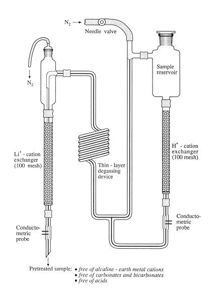
Fig.4-2 Ion-exchange
flow system for pretreatment of drinking water.
Dimensions of columns: length - 100 mm, ID
(H+ column) - 5 mm, ID (Li+ column) - 6 mm. Degassing
device: length of spiral - ~20 cm, ID - 0.7 mm. Conductometric probes (tungsten
wires): 0.5 mm diameter, 2 mm length.
Typical curves of conductometric titration of sulfates in tap water without and with pretreatment are shown in Fig.4-3.

Fig.4-3 Determination of sulfates in tap water.
Conductometric
titrations without and with pretreatment are shown. Water sample - 5.00 ml from
Tel-Aviv University. Medium - 50% ethanol. Titrant - 5.00 mM Ba(OAc)2,
flow rate 0.20 ml/min.
![]() Thin-layer degassing device. Purging of CO2
Thin-layer degassing device. Purging of CO2
The purging of CO2 is carried out
with the thin-layer degassing device2. The solution to be degassed
and an indifferent gas are mixed along a capillary tube (ID = 1 mm and length
30 - 60 cm). The pressure of the indifferent gas is ~0.3 bar, and the flow rate
is adjusted so that the solution is pushed uniformly to the walls of the
capillary, where an invisible thin film is formed. The intimate solution-gas
contact enables an efficient purging of the gas originally present in the
solution, in that case CO2. At the end of the capillary tube the
solution is CO2-free.
![]() Conductometric follow up of ion-exchange-column effluent
Conductometric follow up of ion-exchange-column effluent
The
in-situ measurement of the conductance of the effluent is an efficient tool for
optimizing the working conditions at ion-exchange columns. Several examples are
given:
(a) The conductometric probes at the exit
of the column can fulfill the simple task of indicating the end of the rinsing
stage following regeneration.
(b) In separation processes, it can be used
as a detector as in GC or HPLC.
(c) And finally, in our case, it enables to
follow the gradual changes occurring during the pretreatment of the sample
(cf., Fig.4-4). With the passage of the sample through the columns, the
conductance at the exit of each column increases from zero (the level of
distilled water) to a constant value. At the plateau the composition of the
effluent corresponds to that of the sample, in which all cations are replaced
by H+ or Li+, depending on the type of the column. The
conductance at the exit of the H+ column is higher than that of the
Li+ column, due to next factors: (i) the specific conductance of H+
is considerably higher than that of Li+, (ii) the concentration of
carbonic species at the exit of the Li+ column is equal to zero,
(iii) there may also be variation in the cell constants of the probes.

Fig.4-4 Conductance at column exits during pretreatment
Let
us consider the hypothetical situation, in which a very large volume of the
sample is passed through the columns. The capacity of the column surpassed, the
conductance at the exit of the H+ column would start to decrease and
that of Li+ column - to increase, until equality of specific
conductivity are obtained (explain!).
Typical follow up of the effluent
conductance is shown in Fig.4-4. During the elution the conductance at the end
of each column increases and reaches a plateau. (Explain the differences in
location and height of the two curves). The sample for the titration is
collected at the exit of the Li+ column when a constant value of the
conductance is reached.
![]() Estimation of the maximum volume of sample passed through the exchange
column
Estimation of the maximum volume of sample passed through the exchange
column
When
a quantitative ion-exchange process is required, the amount of sample to be
treated should correspond to not more than ~70% of the column capacity. The
type of ion-exchange process, the type of resin, the size of the resin
particles, the geometry of the column and the flow rate may strongly affect
that value. A rough estimation of the maximum volume of the sample can be made,
if the total concentration of the ionic species is approximately known.
Measurement of the specific conductance, k, of the sample provides an estimate of the total ionic concentration.
Assuming an average equivalent conductivity, L, of 120 ohm-1·cm2·eq-1, the total ionic
concentration in mol/l is
![]()
The recording of the conductance at the output of the columns is an useful indicator of the functioning of the resin.
![]() Determination of the conductometric cell constants of the titration cell
and the ion-exchange columns
Determination of the conductometric cell constants of the titration cell
and the ion-exchange columns
Although not imperative, the knowledge of the cell constants is helpful. If not provided by the instructor, the cell constants may be measured as follows.
Rinse
the cell with a small amount of 1.00 mM KCl. Fill the cell with the same
solution. Measure the conductance. The cell constant is calculated from: kcell
= L/k. The specific conductance, k, of 10 mM KCl at 200C is 1.278
mS/cm, with temperature coefficient 2.14%/K.
4.4. Experimental procedure
Chemicals
1. 1 M HCl
2. 1 M LiCl
3. 5.00 mM Ba(OAc)2
4. 0.5 mM Na2SO4
5. 0.5 mM Na2SO4 + 2
mM Ca(NO3)2
6. 0.5 mM Na2SO4 + 2
mM NaHCO3
7.
Ethyl alcohol
8. Strongly acidic cation exchanger Dowex
50W, 100-200 mesh, 3-5 meq/g dry material
9. 1 mM KCl (for calibration of
conductometric cell)
![]() Titration setup
Titration setup

Fig.4-5 Setup for conductometric titration of sulfates
![]() The regeneration of the ion-exchange columns
The regeneration of the ion-exchange columns
1. Disassemble the columns from the flow
system. Connect to each column a 15 ml reservoir. Connect the columns to a
conductometer. Set the sensitivity of the conductometer and the recorder, so
that the full-scale reading of the recorder is 0.2 S·cm-1.
Set the time scale to 1 cm/min. Start the recording device a few seconds before
the beginning of the regeneration process.
2. For the regeneration of the H+
column use ~10 ml of 1 M HCl and for the Li+ column use ~10 ml 1 M
LiCl. Pass the electrolyte through the resin, applying a small gas pressure to
obtain a flow rate of about 2 ml/min.
3. Rinsing of the columns: use small portions of water to wash the glass walls. If any water is present above the resin allow it to soak into before continuing the washing. Pass about 10 ml water until the conductometric reading drops to the level of the conductance of the distilled water. Compare the specific conductance and not the absolute value of conductance, due to the variety of conductivity cells you work with.
![]() Practicing with the flow system
Practicing with the flow system
In order to get acquainted with the flow pretreatment setup, you should operate it at first with distilled water. Starting conditions:
·
The pressure
of the gas (nitrogen) is adjusted to 0.4 bar. The needle valve is closed.
·
The level of
the liquid in the columns is equal to that of the resin.
·
The reservoir
stopper above the Li+ column is removed. Operating the flow system:
1. Fill the reservoir above the H+
column with distilled water. Place a 50 ml beaker beneath the Li+
column.
2. Slowly open the needle valve. Pressure
is applied on the column and the liquid starts flowing through it. Observe what
happens along the glass helix. At slow flow rates solution and gas are
interlaced. Increase further the flow rate of the gas. The glass capillary
seems to be empty. A thin, invisible film is formed along the capillary. These
are the suitable conditions for the operation of the thin-layer degassing
device.
3. At that stage solution accumulates
above the resin of Li+ column. Place back the stopper of the
reservoir from this column. The solution starts to flow through the column.
Under steady-state conditions the level of the liquid above the Li+
resin should be equal to that of the resin. In order to reach this condition,
close for a short time the gas exit of the thin plastic tube, connected to the
stopper.
4. Estimate the flow rate of the solution at
the exit. If it is lower than 1 ml/min, increase further the gas flow rate. If
solution accumulates in the reservoir of the Li+ column, you need to
increase the flow rate of the solution through that column. First discard the
excess of liquid as described above. Then prolong the plastic tubes for the
outlet of the gas. This increases the pressure applied on the column and so
increases the flow rate. Pay attention that this change did not affect the flow
through the helix capillary. If everything is O.K., you are ready for the real
experiment. Release the pressure by closing the needle valve and open the
stopper above the Li+ column.
![]() Pretreatment of the sample with the flow system
Pretreatment of the sample with the flow system
The
pretreatment of the sample for the determination of sulfates is carried out in
the above flow system. A relatively large amount (up to 30 ml) of a sample can
be introduced through the columns. The front of the sample pushes down the
distilled water, which originally fill the columns. The sample undergoes the
changes described in this chapter, section 4.3. Conductometric probes, located
at the exit of the flow system, are used to follow the progress of the elution.
The conductance changes from that corresponding to distilled water to that of
an effluent with uniform concentration (Fig.4-4). The effluent with uniform
concentration is collected for further analysis. The concentration of the
sulfate in this fraction is identical to that of the original sample.
It
is assumed at that stage that the gas pressure and flow rate of the gas are
adjusted in the previous steps. Check that the level of the liquid in both
columns is equal to that of the resin. Use the conductometric detectors to
ensure that the columns have been thoroughly washed with deionized water.
Place
a 10 ml graduated flask under the outlet. Prepare a 50 ml dry plastic beaker
for collecting the sample. Disconnect the reservoir of the H+ column
and replace it with a dry one, or rinse the original reservoir with a small
volume of the sample to be analyzed. Connect the conductometric probes to a
recording device. Set the sensitivity of the recorder to 100 mS full scale and use a time scale of 500 s.
Introducing
the sample in the flow system. The sample should be introduced at first
in small amounts into the column in order to replace the distilled water
without diluting the sample, located above the resin. Transfer with a Petri
pipette few drops of the sample directly above the H+ column. Apply
a pressure above the column for a short time. Let the solution be absorbed into
the resin. Repeat several times the sequence of addition small amounts of
sample and applying pressure. At that stage there is no more danger of diluting
the sample. Fill the container with about 20 ml of sample. Open the needle
valve. If the setting of the pressure and the flow rate of the gas have been
adjusted correctly in the previous section, the flow rate of the effluent
should be about 1 ml/min, the glass column is free of visible motion of
solution and there is no accumulation of solution above the Li+
column. If not, there is still time to make last adjustments.
Observe
the variation of the conductance at the exit of the flow system. After about 4
ml of solution has passed the column, the reading should be constant with time.
At that point start collecting the effluent for further use. After the required
volume of effluent is collected, close the gas valve. The flow system is ready
for further use if needed.
At the end of the experiment rinse the flow system with distilled water.
![]() Conductometric titration of SO42- with Ba2+
Conductometric titration of SO42- with Ba2+
Transfer
2.00 to 5.00 ml of the pretreated sample into the conductometric cell. Add
ethanol according to the concentration of sulfate in the sample:
for
[SO42-] < 0.5 mM, Vethanol/Vsample
= 1.5;
for
[SO42-] < 0.5 mM, Vethanol/Vsample
= 1.
The total height
of the liquid in the cell should be such that the electrodes are covered, also
when the solution is stirred. The time needed to reach the end point should be
no shorter than 2 minutes. Faster rate of titration may result a delay of the
end point, due to the slow kinetics of precipitation. The concentration of the
titrant Ba(OAc)2 is about five to ten times larger than that of the
sulfate in the original sample.
Get
the recording device ready. Dip the tube filled with the titrant into the cell.
Start the titration by turning on the pump. The titration curve is displayed.
At the end of titration turn off the recording device and the pump.
Repeat
the titration to check the reproducibility.
Titrate
the unpretreated drinking water sample under identical conditions. Refer to the
differences.
Determine
the flow rate of the pump as described in Titrimetric Methods of Analysis,
section 1.6. Report the concentration of sulfate in mmol/l and ppm SO42-.
![]() Effect of interferences
Effect of interferences
You
are provided with three synthetic solutions:
(a) 0.500 mM Na2SO4
(b) 0.500 mM Na2SO4
and 2 mM Ca2+
(c) 0.500 mM Na2SO4
and 2 mM HCO3-
Titrate each solution in presence of ethanol. Discuss the results.
![]() Effect of ethanol concentration
Effect of ethanol concentration
Titrate 5.00 ml of 0.500 mM Na2SO4 using different volume ratios of sample:ethanol (1:1.5, 1:1 and 1:0.5). Discuss the results.
References
1.
E. Kirowa-Eisner, D. Tzur, M. Brand and Ch. Yarnitzky, Microchem. J.,
61, 40(1999).
2.
Ch. Yarnitzky, Electroanalysis, 2, 581(1990).
Exp.2. Conductometric titration of strong and weak acids
Chemicals 1. HCl: 0.1, 1, 10 mM
2. HAc: 1, 10, 100 mM
3. NaOH: 1, 10, 100, 1000 mM
4. 1 mM KCl (for calibration of conductometric
cell)
Electrodes
For precision measurements of conductance platinized-platinum electrodes are used to reduce the polarizing effect of the passage of the current between the electrodes. For the purpose of conductometric titrations, where the end point is to be precisely determined, but the absolute conductance is of lesser importance, other electrodes may be used (bright platinum, tungsten and others).
Titration setup
The titration is performed with continuous addition of titrant using an automatic burette or positive displacement pump or peristaltic pump (cf., Fig.4-5). Viton or tygon tubing (I.D. about 1 mm) are recommended for the peristaltic pump. Read Titrimetric Methods of Analysis, section 1.6 for details of using automatic titrators. Determine the flow rate if a pump is used.
Procedure
1. Determine the conductometric cell
constant as described in Exp.1 of this chapter (Determination of sulfates in
drinking water).
2. Introduce 5.00 ml of acid sample into
the conductometric cell. Titrate with NaOH at a flow rate of 0.8 - 1.2 ml/min.
Perform a series of titrations according to the order and the conditions
summarized in the Table below. Data should be collected for up to 100% excess of
titrant.
3. Plot the graphs and determine the end
point. Refer to the shape of the titration curves. Compare with the
potentiometric titration curves.
4. Calculate the concentrations of the
acids in mol/l.
5. At the end of the working session rinse the pump tube, the cell and the beakers with distilled water.
|
Analyte |
Titrant (NaOH), M |
Maximal conductance* |
|
10-1
M HAc |
1 |
25 mS |
|
10-2
M HCl |
10-1 |
5 mS |
|
10-2
M HAc |
10-1 |
2.5 mS |
|
10-3
M HCl |
10-2 |
0.5 mS |
|
10-3
M HAc |
10-2 |
250 |
|
10-4
M HCl |
10-3 |
50 |
*For conductivity cell with a cell constant
of about 1 cm-1.
Recommended
Literature
A. I. Vogel, Textbook of Quantitative
Inorganic Analysis.
Go to Main Page