This page describes my second I2C interfacing project. For a general overview of I2C and for basic information on how to use I2C devices from a NXT program, see the first part of this series.
This part shows how to construct a pressure sensor for the NXT, one that can measure the pressure in a Lego pneumatic system. This sensor allows the NXT when to turn a pneumatic compressor on and off. For a lot of information on Lego pneumatics, see C. S. Soh's web site. A commercial pressure sensor for the NXT is produced by Mindsensors; it is an analog sensor with a pressure range similar to that of my sensor.
The I2C chip that we'll use is an analog-to-digital converter (ADC). An analog-to-digital converter chip allows you to connect an analog sensor (one that converts changes in some physical quantity to changes in voltage) to a digital communication channel, like the I2C channel of the NXT's input ports. Here we'll use an ADC chip to interface a pressure sensor to the NXT. The pressure sensor runs on 5.1 Volt supply, higher than the 4.3 Volts that the NXT supplies to sensor ports. Therefore, we'll need to use the 9 Volts supply line and step it down to 5 Volts.
Warning: connecting your NXT to any home-made gizmo (like the one described here) can damage it. Beware.
The ADC chip that I used the PCF8591 from Philips. The chip has four analog inputs that it can measure and one analog output (so the chip is both an ADC and a digital-to-analog converter, a DAC). The chip runs on anything from 2.5 to 6 Volts, so it can easily run on the NXT's 4.3V supply.
The chip has four analog inputs that can independently measure voltages between two reference voltages called Vagnd (analog ground) and Vref. These voltages (and the inputs) should not be exceed the supply voltages by more than 0.5v. You can also configure the chip (via I2C programming) to use some of the inputs as differential inputs, relative to one another and not relative to the fixed references. We won't use differential inputs here. In absolute mode, the chip divides the voltage range into 256 equal intervals and represents each measurement using an unsigned byte (in the differential setting, the byte is signed, telling you which input is higher and by how much).
The chip also has one output that you can set to 256 different voltages between Vagnd and Vref. We won't use it here.
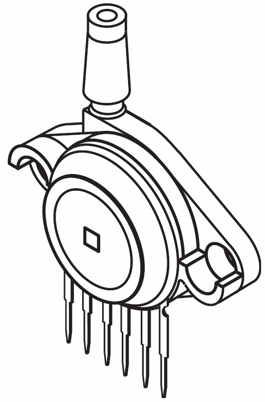
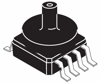
To use the chip, the I2C master addresses it (the four high bits are 1001 and the three lower ones are configurable via pins) and then sends a control byte. The control byte tells the chip how you want to configure the inputs (absolute, differential, or a combination), whether you want to use the analog output, and which input you want to read next. You can also tell the chip to send several input values (from different ADC channels) sequentially. I configured the circuit to use only one input, number 2, I didn't use the analog output, and I only wanted one measurement in each I2C transaction. Therefore, in every transaction I sent the chip the two-byte sequence 0x90 0x02 and received one byte back, representing the voltage at input 2.The pressure sensor that I used is the MPX4250A. It is made by Freescale, and it is designed primarily for automotice applications. It measures absolute pressure, it contains on-chip circuitry for temperature compensation, and it comes calibrated. The chip comes on four different packags: two for soldering onto a printed-circuit board (PCB) and two that plug into a socket and are inteded to be secured with some kind of screws; two with a port (a little nozzle for connecting a hose) and two without a port. For Lego pneumatic applications, we need the versions with a port. The package intended for soldering into a PCB comes in a package called "small outline" which is inconvenient for prototyping (and difficult to solder by hand), so I used the bigger package type, called Unibody.
|
|
| Unibody package (with port) | Small-outline package (with port) |
In principle, this chip is easy to use. Only 3 of its pins are used. One should be connected to ground, one to suply voltage around 5.1 Volts (between 4.85 and 5.35), and the third is the output pin: its voltage indicates the pressure at the port. The output voltage and the pressure are related by the following formula: Vout = Vs* (0.004 x P-0.04), where Vs is the supply voltage and P is the pressure in kPa (kilo Pascals). 101325 Pascals are one atmosphere, and the sensor measures between 0 and 250 kPa, so it can measure pressure up to 2.5 times the normal pressure at sea level.
To use this chip in an I2C sensor, we need to hook its output pin to the input pin of an analog-to-digial converter like the PCF8591, and to make sure that the reference voltage that the A/D converter uses is the supply voltage of the analog sensor pressure. The PCF8591 has a voltage refence pin that I used for this purpose. If the A/D chip uses its supply voltage as the reference voltage, then we would need to use the same supply voltage for the sensor and for the A/D chip.
The MPX4250A needs supply voltage between 4.85 and 5.35 Volts. The NXT supplies 4.3 Volts to all the ports. This is too low for the pressure sensor. My measurements showed that the NXT supplies 4.66 Volts, not 4.3 (Philo wrote to me on the nxtasy.org forum that this voltage ranges between 4.1 V and 4.7 V, so it definitely may be too low). Even if the sensor would not completely fail when powered by this supply, it may function inaccurately; its performance, accuracy, and caliberation is only guaranteed for 4.85 to 5.35 Volts.
Therefore, we need to somehow generate regulated 5.1 Volts (or 5V, which is good enough here) from the sensor port.
We will do this by using pin 1 of the sensor port. This pin is called ANA (analog), which is primarily used for analog sensing by the NXT (it is used with the NXT's light, sound, and touch sensors, as well as with the RCX sensors). When the sensor port is configured for I2C, you can tell the NXT to power this pin. To do so, you configure the port to IN_TYPE_LOWSPEED_9V. When I measured the voltage on this pin in this configuration, I got around 6.75V, not 9V. We will use a simple inear voltage regulator to step down and regulate this voltage to 5V.
In the first prototype I used a standard low-power linear regulator, the 78L05. It worked, but it is not a good idea. This chip requires 7V as input; in my example it did work with 6.75, but it may fail below 7V. This regulator, the 78L05, is a pretty old design. There are newer chips called low-drop linear regulator that need an input voltage that is just a bit higher than the regulated output. Such regulators should work more reliably here; I plan to try a regulator from ST Microelectronics, the L4949V5.
Another consideration when using the ANA pin of sensor ports is the low amount of current that they can supply, 18mA. This is more than enough for the PCF8591 and the MPX4250A (which need 1mA and 10mA max, respectively), but it means that the regulator itself must be pretty efficient (the L4949V5 consumes 5-8mA at low loads, so it is borderline here).
The 18mA current limit also has advantages: since the NXT limits the current to this pin, it cannot damage devices by providing too much power to them. Philo suggested on the nxtasy.org forum that a 5.1V Zener diode can serve as a 5V regulator in this case.
I didn't draw this circuit but rather built it directy from the data sheets onto the breadboard. It uses only three chips: the MPX4250A pressure sensor, the PCF8591 to do the analog-to-digital conversion and I2C interfacing, and a 5V voltage regulator. apart from these, it only uses two 82k pullup resistors (required on the I2C lines according to the NXT documentation) and three bypass capacitors, a 0.22μF on the input side of the regulator, and two 100nF capacitors on the 4.3V and the 5V supplies.
I built the circuit on a simple breadboard. I modified the connection to the NXT from my 8574 prototype: I soldered the 6 wires in the NXT cable to 6 header pins (standard 0.1" pins, like those of DIP chips), which allows me to plug the NXT cable directly onto the breadboard. It's still a little ugly, but mechanically and electrically solid.
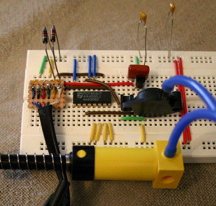 |
You can see the wire that goes to the NXT (the little proto-board on the left), the two 82k pullup resistors and the PCF8591 chip (in the center). The pressure sensor is in the center, and above it you can see the voltage regulator and the three capacitors. The pressure sensor is connected to a Lego pneumatic hose. On the bottom, you can see the yellow Lego pneumatic hand pump and the end of the pneumatic switch that I used for testing. The wiring is a lot neater than my 8574 prototype. |
If you are planning to build a pressure sensor for the NXT (or for some other computer with an I2C communication channel), there are some other devices that you may want to consider.
© 2006, Sivan Toledo