The sensor ports on the NXT support a serial digital protocol called I2C, which was developed by Philips in the 1980's for use in consumer electronics (in television sets, for example). This article describes the use of a simple I2C chip that provides 8 digital I/O ports with the NXT.
Each one of these eight ports can be used as either input or output (and in some restricted ways also as both). These inputs and outputs are binary: they are either on or off. Input ports can be used for touch sensor (switches), for example. Output ports can drive LEDs, and through relays or other devices they can turn motors on or off. In the setup that this article describes, two ports are used to drive LEDs, two other ports are used as inputs, connected to push switches, and four ports remain unused.
The most important thing to realize about this project is that it is VERY SIMPLE. Connecting your NXT to this the interface chip is as easy as electronics experimentation goes, and programming your NXT to communicate with this chip is also easy.
Warning: connecting your NXT to any home-made gizmo (like the one described here) can damage it. Beware.
I2C is a two-wire serial bus. One wire carries a clock signal and one carries the data signals. In simple configurations the bus has one master that can communicate with as many as 128 slave devices connected to the same two wires. Only the master initiates communication. It can send commands to the slaves, and it can query them for data. The slaves only respond to the master; they cannot initiate communication on the I2C bus. (Many I2C chips have an interrupt output that can be used to notify the master that the chip needs some attention, but this is not part of the I2C protocol, and there is no way to use interrupts in the NXT sensor ports.)
Two of the six wires in the NXT sensor ports carry the I2C clock and data signals. The NXT always serves as a master. Another wire carries a 4.3v supply line, two more are grounded (one of them needs to be used if you use the NXT's power). The sixth line is an RCX-type 9v analog sensor line.
I2C chips usually come with a partially-configured bus address. I2C slaves have a 7-bit address (that is why there can be 128 of them on a bus). In many cases some of these bits are set when the chip is designed, and the rest can be configured by connecting specific address pins to either ground or to the supply line.
Communication on the I2C bus follows a simple protocol. The master signals that it wants to send information (a start signal). Then it sends the first byte of the command, which consists of the 7-bit address of the slave the master wants to communicate with, and a read/write bit. If this bit is 0, the master is not expecting a response; this is a write command. If this bit is 1, the master is expecting a response. When the master receives the response it expected, it signals that the communication is terminated (a stop signal). Apart from the first byte of the command, which always consists of the slave's address, the rest of the command structure is specific to each slave chip.
The chip that I used is a basic and low-cost I2C chip from Philips called PCF8574. It provides 8 bi-directional binary ports. The 4 most-significant bits of its address are 0100, and the lower 3 are configurable through pins. It requires a supply voltage of 2.5-6v, so it can be directly connected to the sensor port's 4.3v supply. It can supply 25mA to each port, which means that it can drive LEDs directly. Pairs of outputs can be connected in parallel to drive higher loads.
There are many similar chips from other both Philips and from other manufacturers. Some of them provide 16 rather than 8 ports and some also includes some memory.
Communicating with the PCF8574 is very simply. To set the ports, you send one byte with the chip's address and a 0 read/write bit, followed by a byte that specifies the value of each port. To read the state of the ports, you send one byte with the chip's address and a 1 read/write bit, and the chip responds with a byte in which each bit describes the state of one port. There is just one more detail: to be able to read the value of a specific port, you must first write a 1 into it (set it to high, so that it can sense being pulled to zero).
To connect something to the NXT, you need NXT cables. I converted the plugs on two halves of a a 6-wire telephone line with standard RJ-12 plugs to NXT plugs, according to the instructions published by Philippe (Philo) Hurbain. I deviated a little from his instructions: I used a fine modeling hand saw rather than a power tool to cut the latch, and I used a 10-minute epoxy rather than a slow-cure epoxy to glue the latch back in its new place. The latch of one of my two plugs later came off, so I my technique is not completely reliable. Perhaps it came off because of the weak glue, and perhaps the less accurate cut of the hand saw.
Since LEGO sells original NXT cables at a reasonable cost, using spare original cables is probably a better idea than creating your own cables. If NXT-style sockets became available, they would be ideal for interfacing projects.
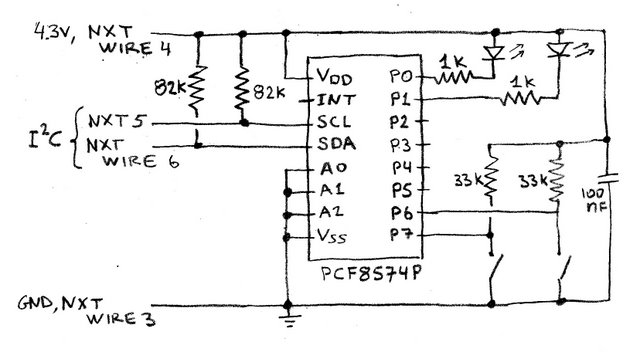
As you can see from the schematic diagram, the circuit is really mostly the PCF8574 chip. The only components on the input side are the two 82k pull-up resistors, which are required according to the NXT Hardware Developer Kit (a PDF document), and the bypass capacitor on the right side of the drawing. Apart from them, there are only two LEDs, each in series with a resistor, and two push switches, each with a pull-up resistor. I wanted to use smaller resistors in both cases, but didn't have the values I wanted; but the resistors I used worked as well. The unused pins on the pins, which include 4 ports pins and the interrupt line, are not connected to anything.
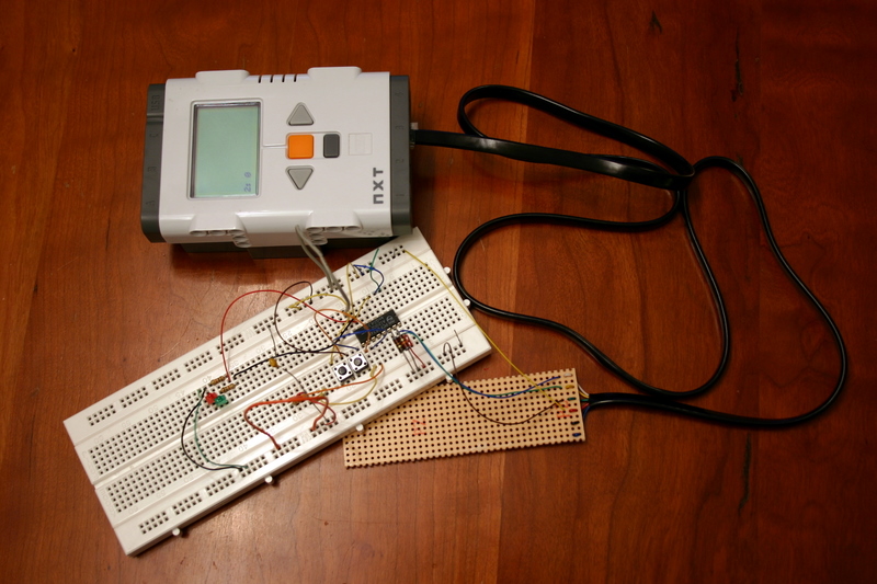
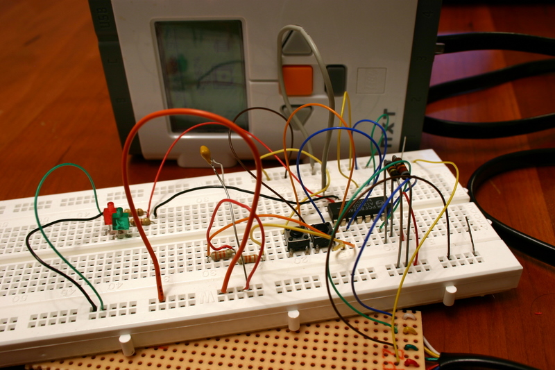
I built the circuit on a simple breadboard. The only difficult part was to connecting the NXT wire. I was not able to reliably connect the 4 wires I needed to the breadboad because there were not stiff enough. So I threaded them twice through a prototyping PCB (to hold them in place), soldered them to the prototyping PCB, and soldered stiffer wires to them. These stiffer wires worked just fine in the breadboard. The PCB is the little yellow board you see in the pictures (most of it is not used).
 |
 |
You can't access the I2C functionality of the NXT from the NXT-G environment. The ultrasound-sensor block in NXT-G does use the I2C functionality, but it is specific to the ultrasound sensor and cannot be used with other I2C chips. Therefore, I used NBC, which does provide access to the I2C system calls.
The firmware provides three system calls to communicate
with I2C
chips. Before you can use them, you must configure the sensor port
to I2C
mode using setin commands and wait
for the configuration to take effect. One system call, CommLSCheckStatus,
simply checks whether the previous attempt to communicate with
an I2C
device was successful. If it returns error 32, then the previous
communication attempt is still pending and you must wait. If it returns
a negative number, then there is some error. Some errors are fatal, but
sometimes you can simply try again. My program does not handle all the
error cases properly. In particular, it just ignores negative errors
(not a good idea). The second system call, CommLSWrite,
is the one that actually initiates communication. It is used to send
commands to an I2C slave and to query it for
data. When you call it, you specify how many bytes should be in the
slave's response. If you specify 0, this means that you are simply
sending a command to the slave and expect no reply (but the slave
always acknowledges communication as part of the protocol; this helps
the NXT know whether the slave is working properly or not). If you
request a positive number of bytes back, the NXT sends the command and
waits for the slave to respond. It keeps the slave's response in an
internal buffer, from which you can retrieve the data using the third
system call, CommLSRead. This system
call does not query the slave; it just retrieves previously sent
information from the firmware's internal buffer.
The only surprise I encountered was the way the firmware handles the read/write bit. I was able to set the output ports (to toggle the LEDs) without a problem by writing a message containing 0x40 (the address of the 8574 slave in my circuit with a 0 read/write bit) and a second byte specifying the desired state of each port. I assumed that to read the state of the ports, I need to send a one-byte message containing 0x41 and expecting a one-byte reply. The value 0x41 consists of the 7-bit address of the slave and of a 1 in the read/write bit position. This didn't work. Eventually I discovered that I need to send 0x40. Apparently, the firmware adds the read/write bit. (I assume that it it adding it arithmetically rather than by or'ing it, otherwise 0x41 would have worked.) Once I figured that out, everything worked fine.
Here is the final NBC program (it doesn't do much, just tests the circuit).
To give you a sense of how easy or difficult it is to interface I2C chips to the NXT, I'll tell you what was my biggest problem (apart from the read/write bit confusion and the difficulty of connecting the NXT wires to the breadboard). After I wired the circuit and wrote the program to toggle the LEDs, I ran it and nothing happened. So I added code to display the error codes from the system calls, and discovered that the firmware was reporting error -35, a bus error, which can indicate a device failure. I started to check voltages in the circuit with a voltmeter, and eventually discovered that the chip was not getting the full supply voltage. I looked at it carefully and discovered that I didn't push it all the way into the breadboard. This shows you that
So my own conclusion is that interfacing I2C chips to the NXT is pretty easy even if you have very little background in electronics. But since things rarely work the first time around when you prototype, you do need to be able to do basic troubleshooting on a circuit (mainly to test connections).
© 2006, Sivan Toledo