Stepper
motors are interesting
actuators. Unlike common DC motors (the class of motors that include
all the Lego motors), they usually have several windings (coils) and
more than two contacts. But activating the windings in a specific
order, a controller can cause the motor to move in concrete steps. The
behavior of steppers in a system is quite different than that of DC
motors; more on that below.
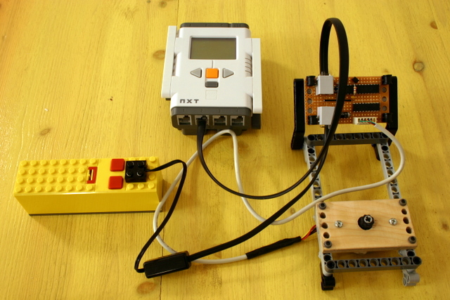
In this project I interfaced a stepper from an old scanner to
the NXT. By interfacing, I mean here both electrically and
mechanically. In fact, the mechanical part is the more challenging
here. You can watch the movie on the right to get a sense of
how the stepperr behaves. The program running on the NXT tells the
stepper to rotate 24 steps, which are 180 degrees, clockwise, wait 2
seconds, rotate back, and so on.
The stepper is controlled by an interesting pair of chips,
an I2C
digital I/O chip, the MCP23016, and an array of 8 Darlington pairs, the
ULN2803. The MCP23016 (and its smaller sibling, the MCP23008)
are better in this application than a PCF8574, because it can source up
to 25mA per I/O pin, whereas the PCF8574 can only source 100uA, which
means that it cannot drive the Darlingtons directly
without strong pull-up resistors.
Warning: connecting your NXT to any home-made
gizmo (like the
one described here) can damage it. Beware.
The Motor
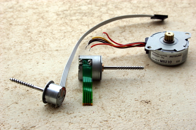
The
picture on the right shows three stepper motors that I tried to use.
The ones in the middle and on the left are from 3.5" floppy-disk
drives. For some reason I could not get them to work properly. The one
on the right is the one I ended up using. It comes from an old flat-bed
scanner.
There are different several types of steppers. You can usually
distinguish between them using an Ohmmeter. The excellent
stepper-motor tutorial by Douglas Jones describes the
different types and how to drive them, so I won't repeat this here.
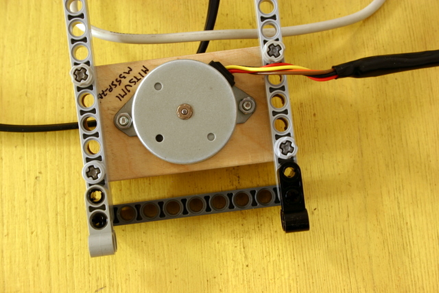
My stepper turned out to be a 4-phase unipolar stepper with
4 windings. One endpoint of each winding is connected to a common wire,
so there are 5 wires altogether coming out of the motor. Each winding
is actually
used 12 times around the motor, which gives 48 steps of 7.5 degrees
each. When current flows between the common connection and one of the 4
endpoints of the windings, this creates a magnetic field that causes
the rotor to align with that winding. If current stops flowing in that
winding but starts flowing in an adjacent one, the rotor will step to
align with the energized winding. By energizing the windings in one
cyclic order, say 1-2-3-4-1-2-3-4, we cause the motor to rotate in one
direction, and by energizing them in the opposite cyclic order
1-4-3-2-1-4-3-2 we cause the motor to rotate in the other direction.
The rotation is discrete, in steps of 7.5 degrees. When one winding is
energized continuously, the motor is stopped and will hold its position
up to some level of torque.
Interfacing the motor to the Technic system is challenging.
The hard part is to interface the shaft, on which a brass gear was
mounted, to Technic axles. I followed advice by Philo to use
heat-shring tubing and glue to secure some Technic part to the brass
tubing. I used an 8t Technic gear and 8mm heat-shrink tubing. When
shrunk, the tubing gripped the Technic gear very firmly, but it didn't
grip the brass gear very firmly. I added another layer of heat-shrink
tubing around the brass gear, which improved the situation, and secured
the whole thing with a bit of hot glue. This structure now transfers
torque to the Technic gear very well, but it still came off when I made
the movie above. I can still put the tubing back on the brass gear and
it will trasfer torque, but it's not a very solid construction. Perhaps
epoxy, which Philo also suggested, would have worked better.
The mounting for the motor was easier. I
cut two rectangles of
4mm plywood to size (the sides are multiple of 8mm) and glued them
together. I then drilled a large hole for the motor shaft and the
gears, two small holes for the mounting screws, and 5
Technic-compatible holes on each side. I only used hand tools. There
was quite a bit of chipping when I drilled the Technic holes near the
edges of the board, since they are so close. In hindsite, it would have
been much better to first drill the holes and then to cut the plywood
to size. In any case, the resulting assembly is very strong and easy to
connect to Technic constructions. Even a single 4mm board would
probably have been sufficient.
The Controller
I initially
intended to use discrete MOSFET's to drive the stepper, driven by
either a PCF8574 or by a microcontroller. But Michael Gasperi suggested
on a nxtasy.org forum a better solution, the ULN2003. This chip
contains 7 Darlington pairs that can each sink 500mA, and each output
comes with a built-in protection diode. Because the Darlington pairs
use bipolar transistors, you need to push more than 1mA into an input
of the ULN2003 to saturate the corresponding output. The PCF8574 is not
good at pushing current. It can sink 25mA (that is, 25mA can flow into
an ouput that is held low), but it can only source 100uA, not enough to
drive a bipolar Darlington directly. Michael circuit used pull-up
resistors to provide the extra current. This solution works, but it
consumes several mA of current per Darlington even when it is off.
The MCP23016 is an I2C
16-port digital I/O chip; the MCP23008 is similar, but has only 8 I/O
pins. ou can configure each pin in these chips as input as output.
Unlike the PCF8574, it can both source and sink 25mA per output pin.
They have several other functions, like generating interrupts on input
change and capturing the state of the inputs when a change occurs, but
these are not useful with the NXT because it does not have interrupt
inputs. The two sibling chips are not identical, and the MCP23008 has
more features, like programmable pull-up resistors on input-pins.
Another difference is that the MCP23016 uses an internal oscillator
that requires an external resistor and an external capcitor, increasing
the part count somewhat. Both chips are about as power-efficient as the
PCF8574, which uses 10uA at standby: the MCP23016 uses 25uA, and the
MCP23008 only 1uA. Both come in large DIP packages, which I used, and
in several smaller packages.
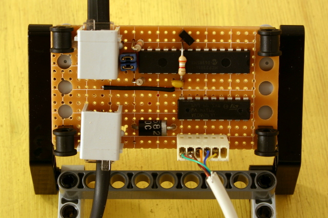
In my controller, I used a ULN2803, which is similar to the
ULN2003 but has 8 Darlington pairs rather than 7, and an MCP23016.
Therefore, the controller can drive two steppers of the same type, or
it can provide twice as much power to a larger stepper (by connecting
Darlingtons in parallel), or a stepper and solenoids, etc. You can
drive all the Darlington pairs of the ULN2803 using the smaller
MCP23008, but I wanted to leave some I/O pins available for sensor
input, say a switch or a Hall-effecct sensor, to sense the position of
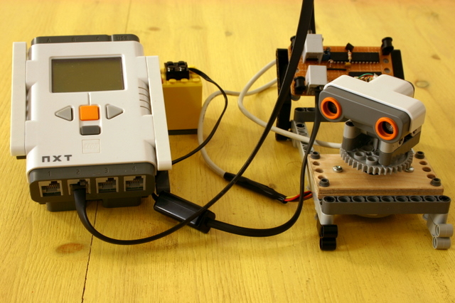
the stepper. Power is provided to the stepper from a NXT socket that is
connected either to a 9V batter pack (using a converter cable) or to a
NXT motor port. The stepper is connected to the controller using a
6-pin polarized header (but only 5 pins are used). The I2C
pullup resistors are connected to the 4.3V supply line through jumpers,
to allow them to be disconnected if the controller is used in parallel
with additional I2C circuits on the
same NXT sensor port.
I used a Schottky diode between the external power supply and
the ULN2803, to protect the chip from negative voltage. But since it is
a bipolar device, I don't think that negative voltage will harm the
chip, and with its collector at a lower voltage than the emitter, I
think that the Darlington will simply shut down.
Steppers vs DC Motors
As I wrote above, steppers behave quite differently
from DC motors, even when the DC motor is coupled with an encoder, like
the NXT motors.
Control of Speed and Power.
This is where steppers really excell. In a DC motor, you cannot control
speed elecctrically. You can control the power that is provided to the
motor by adjusting the duty cycle of a PWM controller (or by
controlling current in some other way), but you cannot control speed.
The speed depends on the relationship of motor power to the extrenal
mechanical resistance. In particular, this means that you cannot cause
a DC motor to rotate slowly but to generate a lot of torque by
controlling the current in the motor; you need to gear down
mechanically to achieve low speed and high torque simulteneously. If
you just provide less power, the motor will usually turn slower, but it
will also have little torque. In a stepper, you control speed and power
separately. The current that you provide to the windings control the
torque: the force that the motor applies to turn or to hold its
position. The rotation speed is determined by the rate at which you
move current from one winding to the next. At least for relatively slow
speeds, the speed is independent of the torque.
Smoothness of Movement.
A stepper moves in steps, so normally, its movement is not smooth. A DC
motor moves smoothly. It is possible to move some steppers smoothly,
but this requires a more complex controller than the one I used here.
See Jone's tutorial for details.
Braking.
Shorting the wires of a DC motor causes it to brake. Depending on the
motor and the gearing, the braking action may not be very strong (it
may not require much force to turn it), but it does not require any
extrenal power. A stepper, on the other hand, holds its position when
current flows through one of its windings. This requires
extrnal power in the break state (which uses up your battteris), but
the holding torque is strong.
Position Control.
You can only know the position of a DC motor if it is coupled to an
encoder, as in the NXT motors. To turn a certain number of degrees, you
apply power and monitor the encoder. When the rotation reaches
the desired position, you brake or float the motor. If you apply full
power all the time, the motor will overshoot the desired position. You
can rotate it back to the desired position, but this correction is not
always acceptable. To reach the desired position without overshooting,
you need to power down the motor gradually, providing less speed and
(and less torque) as you get closer. In a stepper, things are much
simpler. You simply determine the number of steps to reach the desired
position and activate the windings accordingly. In principle, no
feedback is necessary. One catch is that you need to know from which
winding to start. To work reliably, you must know which winding is just
opposite the rotor. If you don't, you cannot count steps
correctly and you might also produce an initial jerky movement (as you
can see in the video above). The trouble is that when you turn on the
system, you usually have no idea which winding is opposite to the the
rotor. Therefore, you need some feedback mechanism to determine that.
You turn the motor, possibly with an initial jerk, until it hits a
limit switch, or activates a Hall sensor or a photo-interrupter. This
is your initial position, and you now know which winding the rotor is
at. So steppers usually need some form of feedback, although
not continuous feedback.
Slipping.
When the external mechanical resistance exceeds the torque that the
motor generates, any motor stalls, both steppers and DC motors. In a DC
motor coupled to an encoder, you know that this has happened. In a
stepper without an encoder, you do not. So to control position using a
stepper without an encoder, the external force must not exceed the
stepper's torque. In a single-purpose design, like a scanner or disk
drive or a printer, this constarint is part of the design
stage. With the NXT, you will need some trial and error to ensure that
that stepper steps reliably in your construction.
Shutting Down Add-On Actuators
The NXT has a useful feature that you hardly notice: when a
program shuts down, the NXT shuts down all the motor ports. So if your
robot misbehaves, you can always stop the program using the gray button
and all activities stop.
This is not the case with NXT-controlled actuator that have a
separate power source, like a battery pack. They can continue to
operate and drain battery energy even when the program
stops. This
is a particular problem with steppers, since they can consume
considerable amounts of power when just holding a fixed position. So
you may not see anything moving, but the motor may be drawing current.
So
you have to be careful and shut them down separately.
 The
picture on the right shows three stepper motors that I tried to use.
The ones in the middle and on the left are from 3.5" floppy-disk
drives. For some reason I could not get them to work properly. The one
on the right is the one I ended up using. It comes from an old flat-bed
scanner.
The
picture on the right shows three stepper motors that I tried to use.
The ones in the middle and on the left are from 3.5" floppy-disk
drives. For some reason I could not get them to work properly. The one
on the right is the one I ended up using. It comes from an old flat-bed
scanner.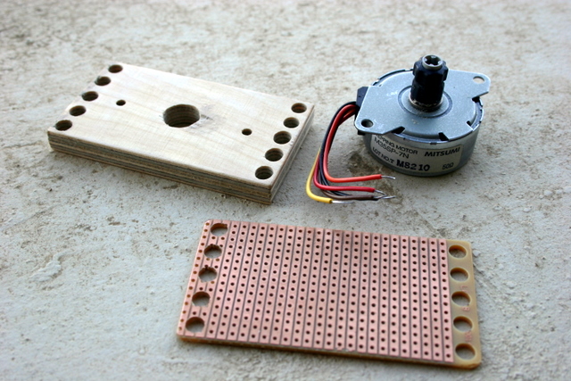 Interfacing the motor to the Technic system is challenging.
The hard part is to interface the shaft, on which a brass gear was
mounted, to Technic axles. I followed advice by Philo to use
heat-shring tubing and glue to secure some Technic part to the brass
tubing. I used an 8t Technic gear and 8mm heat-shrink tubing. When
shrunk, the tubing gripped the Technic gear very firmly, but it didn't
grip the brass gear very firmly. I added another layer of heat-shrink
tubing around the brass gear, which improved the situation, and secured
the whole thing with a bit of hot glue. This structure now transfers
torque to the Technic gear very well, but it still came off when I made
the movie above. I can still put the tubing back on the brass gear and
it will trasfer torque, but it's not a very solid construction. Perhaps
epoxy, which Philo also suggested, would have worked better.
Interfacing the motor to the Technic system is challenging.
The hard part is to interface the shaft, on which a brass gear was
mounted, to Technic axles. I followed advice by Philo to use
heat-shring tubing and glue to secure some Technic part to the brass
tubing. I used an 8t Technic gear and 8mm heat-shrink tubing. When
shrunk, the tubing gripped the Technic gear very firmly, but it didn't
grip the brass gear very firmly. I added another layer of heat-shrink
tubing around the brass gear, which improved the situation, and secured
the whole thing with a bit of hot glue. This structure now transfers
torque to the Technic gear very well, but it still came off when I made
the movie above. I can still put the tubing back on the brass gear and
it will trasfer torque, but it's not a very solid construction. Perhaps
epoxy, which Philo also suggested, would have worked better.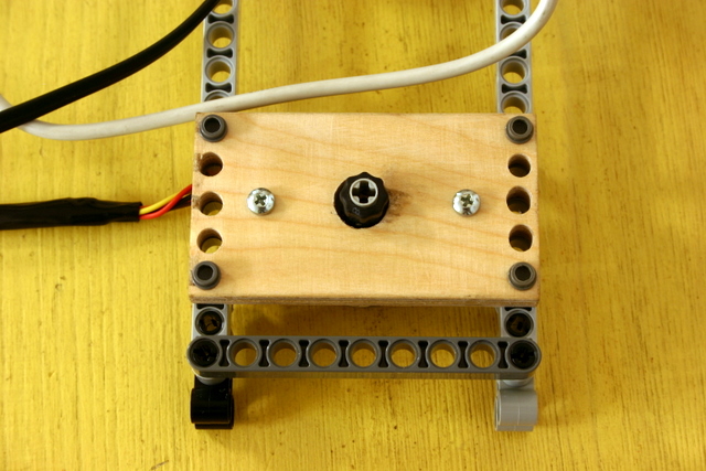
 I initially
intended to use discrete MOSFET's to drive the stepper, driven by
either a PCF8574 or by a microcontroller. But Michael Gasperi suggested
on a nxtasy.org forum a better solution, the ULN2003. This chip
contains 7 Darlington pairs that can each sink 500mA, and each output
comes with a built-in protection diode. Because the Darlington pairs
use bipolar transistors, you need to push more than 1mA into an input
of the ULN2003 to saturate the corresponding output. The PCF8574 is not
good at pushing current. It can sink 25mA (that is, 25mA can flow into
an ouput that is held low), but it can only source 100uA, not enough to
drive a bipolar Darlington directly. Michael circuit used pull-up
resistors to provide the extra current. This solution works, but it
consumes several mA of current per Darlington even when it is off.
I initially
intended to use discrete MOSFET's to drive the stepper, driven by
either a PCF8574 or by a microcontroller. But Michael Gasperi suggested
on a nxtasy.org forum a better solution, the ULN2003. This chip
contains 7 Darlington pairs that can each sink 500mA, and each output
comes with a built-in protection diode. Because the Darlington pairs
use bipolar transistors, you need to push more than 1mA into an input
of the ULN2003 to saturate the corresponding output. The PCF8574 is not
good at pushing current. It can sink 25mA (that is, 25mA can flow into
an ouput that is held low), but it can only source 100uA, not enough to
drive a bipolar Darlington directly. Michael circuit used pull-up
resistors to provide the extra current. This solution works, but it
consumes several mA of current per Darlington even when it is off.