Answer to the Question 02/97
The question was: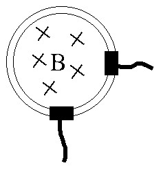 Flux of the magnetic field B through a metalic ring is changing
with time. It creates 12 Volt electromotive force in the ring.
A voltmeter is connected to the contacts shown in the picture, i.e.
the contacts are are separated by 1/4 of a circle.
What will be the reading of the voltmeter?
Flux of the magnetic field B through a metalic ring is changing
with time. It creates 12 Volt electromotive force in the ring.
A voltmeter is connected to the contacts shown in the picture, i.e.
the contacts are are separated by 1/4 of a circle.
What will be the reading of the voltmeter?
The problem was solved correctly by Itamar Borukhov, Eilon Brenner, Boaz Kol and Udi Fuchs from Tel Aviv U. (4/6/97).
The answer: if the voltmeter is positioned in the lower-right corner outside the ring, then it will show 3V, while if it is positioned in the upper-left corner outside the ring, then it will show 9V.
The outline of the solution is as follows:
1. Since this is NOT an electrostatic problem it is impossible to define potential differences (voltages). Neverthless the integral of the electric field E along a certain segment (electromotive force - EMF) of a ring plays a very similar role: Since the Ohm's law is still valid (current is proportional to the local field, therefore the sum of resistances of segments of circuit multiplied by currents must be equal to the EMF in that circuit. However, the EMF is equal to the rate of change of flux within that specific loop.
2. Voltmeter has high internal resistance an measures the current flowing through it. It displays on its scale the current multiplied by internal resistance (that's what we call "reading of the voltmeter").
3. The current is conserved at every junction.
4. One needs to choose two loops in the electric scheme and apply the above laws.
Here is what Borukhov, Brenner, Kol and Fuchs actually wrote:
The answer depends on the geometry in which the Voltmeter is connected to the circuit. For example, if the Voltmeter was connected to the same points, but this time from the other side of the ring - it would read 9V.
The subtle point is that the voltage is not a local quantity but rather a global one depending on the amount of flux circled by the current loop. Therefore one has to solve for the current passing through the Voltmeter.
One way to solve the problem is to look at closed current loops using Kirhoff's law (see Figure). [Note: the "power sources" in the figure are "symbolic" - they denote integrals of electric field.]
For example, suppose we want to solve for the currents using the top and bottom loops. Then the equations would be:
top: 12V = 3/4*R*I1 + 1/4*R*(I1-Ir)
bottom: 0 = Ir*r + 1/4*R*(I2-I1)
which gives in the limit r>>R: Ir*r = 3V
If we want to use the top circuit and the external one then we get:
top: 12V = 3/4*R*I1 + 1/4*R*(I1-Ir)
external: 12V = 3/4*R*I1 + Ir*r
which gives the same result.
 Back to "front page"