Perfect Pitch: An Accurate-Pitch Sensor and Sounder
 The
circuit in the picture is a sound sensor that measures both the overall
strength of sound and the amount of audio energy in a specific
frequency of up to 4kHz. This allows it to detect whether a tone of a
particular frequency is played: it compares the audio energy in that
frequency to the total amount of energy, and if the ratio is high
enough, say above 1/8, it concludes that somebody is playing the tone.
The
circuit in the picture is a sound sensor that measures both the overall
strength of sound and the amount of audio energy in a specific
frequency of up to 4kHz. This allows it to detect whether a tone of a
particular frequency is played: it compares the audio energy in that
frequency to the total amount of energy, and if the ratio is high
enough, say above 1/8, it concludes that somebody is playing the tone.
The device can also produce a fairly strong tone at a 2048Hz
using a small electromagnetic sounder (the kind that's used in alarm
clocks, ovens, etc.). That way, several robots each equiped with such
devices can communicate audibly: when one produces a tone, the others
can detect it. This should allow them to communicate via Morse code,
for example (and would allow people to hear this communication).
Almost all the processing in the device is done digitally.
This includes both the detection of the tone and the generation of an
frequency-accurate tone. The analog sections are very simple.
The device communicates with a master (a NXT) via I2C.
The master can tell it to start and stop producing sound, it can tell
what frequency to detect. The device can report to the master the total
amount of sound energy in the last period of sampling (right now about
1/40 of a second) and the amount of energy in the frequency it is tuned
to.
Warning: connecting your NXT to any home-made
gizmo (like the
one described here) can damage it. Beware.
Overall Design
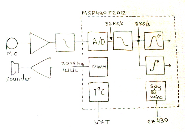
The overall structure of the system is shown in the figure
below. The sound is picked up by a microphone and amplified (the
right-pointing triangle). It is then passed through a low-pass filter
that serves as a simple anti-aliasing filter. This signal is sampled by
the analog-to-digital converter (ADC) of the microcontroller, an
MSP430F2012 from Texas Instruments. The signal is sampled at 32768
samples per second. These sampled are passed through a digital low-pass
filter that produces 8192 samples per second at its ouput.
These 8ks/s samples are processed by an algorithm called the
Goertzel algorithm (the box marked G in the figure). This algorithm
computes a single Fourier coefficient. This coefficient tells us how
much energy the input signal had at a particular frequency. The main
useful feature of this algorithm is that it does not need to store the
samples; it processes them one at a time. This allowed me to implement
the algorithm on a processor with only 128 bytes of memory. A full FFT
would have required the storage of all the samples, which is impossible
on this processor (and might have been too slow to process the samples
in real time). Only two numbers which can be stored in RAM, determine
the center frequency of the Goertzel algorithm, which allows the
I2C. master to send the numbers for
arbitrary frequencies.
The samples are also integrated in order to measure the total
sound energy in the signal. This allows us to compare the sound energy
at a particular frequency to the total amount of energy in the signal.
To generate a tone, we use a pulse-width modulation (PWM)
output of the processor. The PWM peripheral is programmed to generate a
2048Hz square wave with a 50% duty cycle (high for 50% of the cycle).
This signal is fed to a switching transistor (shown as an amplifying
triangle in the figure) that turns an electro-magnetic on and off.
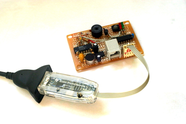
The F2012 communicates with the NXT through an I2C
interface. To program the chip (and to debug the program running on
it), the circuit is connected to an ez430 USB programmer though a
home-made extension cord.
The system also contains a few more components not shown in
the block diagram. A Maxim MAX604 produces 3.3V regulated power from
the NXT's 4.3V supply line. A 32kHz crystal is used by the F2012 for
accurate timing of the PWM signal and of the ADC sampling. Two LED's
provide visual feedback of tone detection and program failure, and a
push switch also helped in the development of the program. The LED's
and the switch are connected to the F2012; the LED's through
560Ω resistors and the switch directly.
The Goertzel Algorithm
The key element in the design is the Goertzel algorithm, which
computes a single Fourier coefficient.
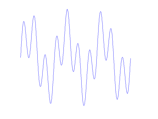
Periodic signals can be described as a time series of
amplitudes, but also as a linear combination of sines and cosines. for
example, the figure below shows a periodic signal. We can represent it
as a time series x(t), where t is time, or as a sum of two sines,
x(t)=sin(3t)+sin(10t).
A Fourier transform is a
mathematical operation that takes a signal (continuous or sampled) as a
time series and represents it as a linear combination of sines and
cosines at particular frequencies. The fast Fourier
transform (FFT) is a family of particularly efficeint algorithms that
computes all the Fourier coefficients of a sampled signal. The FFT is
not appropriate for our purposes. First, although it is efficient, it
requires more work (arithmetic operations) than computing a single
Fourier coefficient. Second, it requires us to store all the samples;
the F2012 does not have enough RAM to store tham. Third, it works
particularly well on sample sizes that are powers of two and it
produces Fourier coefficients for equidistant frequencies (0, 1, 2, 3,
and so on). This reduces its flexibility: if we want the Fourier
coefficient of 1532Hz from 197 samples of a signal, the FFT is not a
good computational tool.
The Goertzel algorithm is a
clever way to compute a single Fourier coefficient. It can compute the
coefficient of any frequency from a sample size of any size. It uses
only two multiplication per sample, and it only needs one sample at a
time. Because it only uses one sample at a time, in sequence, it can
process the samples as they come. Once a sample has been processed, we
don't need to store it any more. The algorithm uses only a few
variables. Some of them carry information from one sample to the next,
and two of them are fixed numbers (a sine and a cosine) that determine
the frequency of the coefficient that is computed.
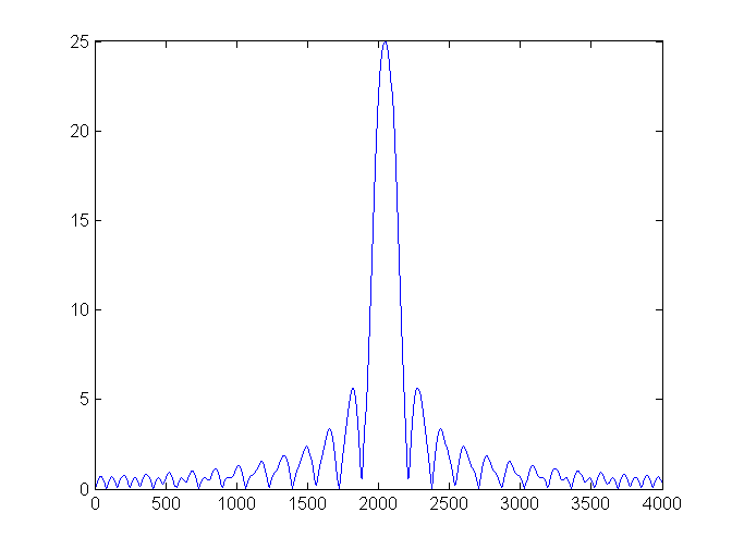
Windows
To use the Goertzel algorithm, or most other signal processing
algorithms, we chop the infinite stream of samples into fixed sized
windows and run the algorithm on each window. In Fourier transforms,
the size of the window determines the frequency range of the response.
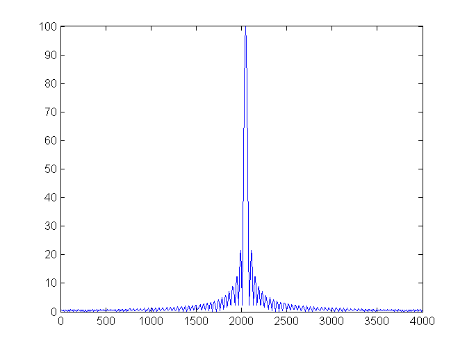
In the figure below, we show the magnitude of the Fourier coefficient
of 2048Hz for pure-sine signals of frequencies ranging from 0 to 4kHz.
The window size is 50 samples.
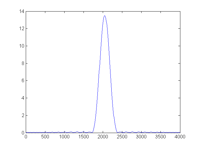
If we process the same signals using a window of 200 samples,
the response becomes much more localized.
This is better if we want to
detect a very specific tone. The main down side of using more samples
is that it will take us longer to detect the tone.
Both of these response curves
show that the Fourier coefficient responds not only to the frequency it
is tuned for, but to many other frequencies as well, even very far from
the tuned frequency. The response weakens as we get further away from
the tuned frequency, but it does not decay quickly. The reason for this
is that most of the signals that we tested are not periodic when
chopped into a window of 200 samples. To get a fast decay, we need to
coerce the signal that we have in the window into a periodic one. This
is done by scaling down all the samples. The samples at the endpoints
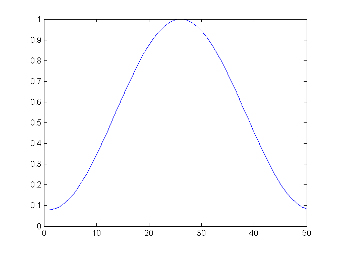
of the window are scaled almost to zero. There are several formulas for
such scalings; I used a formula called a Hamming window. Here are the
scaling values for a window of 50 samples.
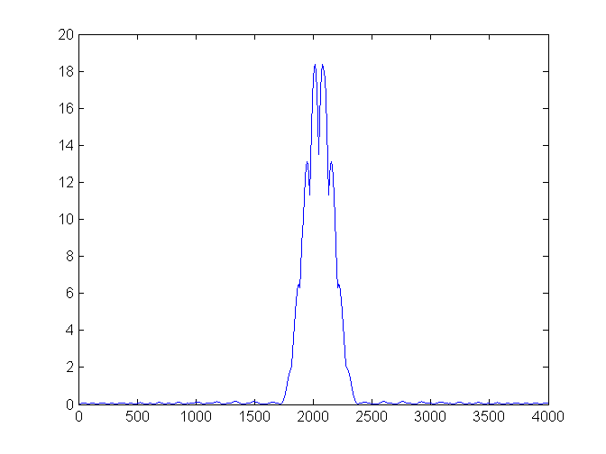
If we apply the Hamming
scaling window to our signals and then compute the Fourier coefficient
of 2048Hz, we can the following response curve.
You can see that
the decay to zero away from the center frequency is much
stronger, but on the other hand the coefficient responds to more
frequencies near the center. This is the price for the decay to zero
further away.
Using the Hamming window
requires storing its coefficients. They are stored in a constant array,
so they reside in flash, not in RAM. Flash is much larger than RAM on
the F2012 (and on most other microcontrollers), so we can store the
coefficients for a large window. The window coefficients depend only on
the window size, not on the frequency that we want to detect.
Therefore, the same window coefficients are used even if we change the
center frequency dynamically.
The computation cost of using
a Hamming window is one multiplication per sample.
Norms
The amount of energy in the input signal is the square root of
the sum of squares of the samples. This is also called the two-norm of
the signal. But computing it requires one multiplication per sample,
and if we accumulate the squares, the numbers involved are large.
Therefore, I approximated the energy by the sum of squares of the
samples. This is less accurate, but should usually be good enough.
Similarly, the energy represented by a Fourier coefficient is
the absolute value of the coefficient, which is a complex number. I
again approximated this by the sum of squares. This introduces some
artifacts in the response curve, but it is good enough for us, and it
is faster. Here is the response curve.
Fixed Point and DSP without a Multiplier
The response curves that we have seen up to now computed the
Fourier coefficient using floating-point arithmetic on a PC.
Microcontrollers do not support floating-point in hardware, so if you
implement the algorithm using floating point (float
or double in C), it will either not compile,
or it will compile but run very slowly. So we need to use integer
arithmetic. Fourier analysis requires fractional numbers, so we will
represent them using integers by imagining that the binary point is in
the middle of the number, not to the right of the rightmost digit. This
is called fixed point arithmetic.
The registers of the MSP430 processors are 16-bit wide, so
arithmetic on 16-bit integers runs much faster than on 32-bit integers.
Nonetheless, it is hard to implement algorithms with small word sizes.
If you place the binary point too much to the right, you loose
accuracy. If you place it too much to the left, you get overflows,
which are really catastrophic. When an overflow occurs in a fixed-point
algorithm, the results are usually completely wrong. In Fourier
algorithms, one of the things that determine the largest numbers that
show up in the algorithm is the length of the window. As the window
grows larger, the Fourier coefficients (and intermediate results) get
larger. The other thing that determines the range of numbers is the
accuracy of the ADC; the more bits it provides in each sample, the
larger the integers in the implementation of the signal-processing
algorithm.
It is probably possible to implement the Goertzel algorithm on
the F2012 on useful window lengths in 16 bits, but it is hard. I did a
few experiments and decided that it was really on the border of what
you can do with 16 bits. On small window sizes I got good results, but
on longer the algorithm overflowed and produced junk. Therefore, I
decided to use 32-bit integers. This really slowed down the algorithm,
but it can stil handle more than 8000 samples per second. With 32-bit
arithmetic, you can safely use large windows (I use 200).
The arithmetic unit on the MSP430 processors is pretty weak.
It only operates on 16-bit numbers, so operations on 32-bit integers
require several instructions (the C compiler generate them
automatically). Some of the high-end MSP430's have a hardware
multiplier, but the F2012 does not. Therefore, multiplication is
performed using a library function that uses repeated addition. This is
really slow. I used the simulator that comes with one of the free
development environments (IAR Embedded Workbench) to see how long
32-bit multiplications take. I observed running times between 100 and
300 cycles. The running time depends on the number of leading zeros in
the first multiplicand, so it helps to try to get the first
multiplicand to be positive and smaller. For example, to multiply a
sample by a Hamming coefficient, you should place the Hamming
coefficient first in the multiplication.
The algorithm performs 3 multiplications per sample and a few
other operations (mainly additions and shifts). It can keep up with
8000 or 8192 samples per second, but just barely. I run the processor
at 16MHz, which means that the algorithm has a bit less than 2000
cycles to process each sample. I added to the code a conditional that
lights a red LED if it fails to keep up with the incoming cycles. If I
order multiplications so that the smaller number is the first
multiplicand, the processor can keep up. But if I flip the order of
multiplications by the Hamming window, it fails to process the samples
on time.
Anti-Aliasing
Digital signal processing (DSP) provides correct results only
if the highest frequency component of the signal is at most half the
sampling frequency. Higher frequencies in the analog signal look like
lower-frequency components that are not really present in the signal.
This phenomenon is called aliasing and you need to minimize it in order
to get useful results from a digitized signal.
To avoid aliasing, you need to filter high-frequencies from
the signal. This filtering is called anti-aliasing. Some of this
filtering must be done in an analog circuit, because one you sample the
signal, you cannot remove antialiasing that has already occured.
Ideally, we would use a filter that does not attenuate or
distort frequencies below half the sampling frequency fs,
but that completely cuts out frequencies just above fs/2.
Unfortunately, there are no such filters. The attenuation of simple
low-pass filters increases with frequency only mildly, so to avoid
antialising, you need to start filtering at a frequency much smaller
than fs/2. More sophisticated analog filters
have a more steep dropoff, but they are harder to design and build. The
most common filters, called active filters, require a lot of accurate
and stable resistors and capacitors if you want to get a steep drop
off. Another kind, called a switched-capacitor filter is much easier to
use, but requires a clock that must be synchronized with the clock of
the analog-to-digital converer. Therefore, it is somewhat challenging
to interface.
I decided to use an anti-aliasing approach that is partially
analog and partially digital and easy in both domains. It was suggested
in two application notes from Texas Instruments that show how to sample
audio on the MSP430.
It works like this. The analog part of the system only
includes a simple low-pass filter (I used just a single stage RC
filter; you can use more stages and/or some other filtering scheme).
The goal of this antialiasing is to pass signals below 4kHz (the
pass-band) and to filter signals above 16kHz (the stop-band). We don't
care about signals between 4kHz and 16kHz, as long as they are not
amplified. This lax specification of the filter is what allows us to
use a simple filter.
We sample the signal at 32768 samples per second. This is why
we need to filter well anything above 16kHz. There is no point in
running the Goertzel algorithm at this rate (even if the processor
could do it, which it cannot, at least not in 32-bit fixed point),
because we do not care about very high frequencies. What we will do is
to sum every sequence of 4 samples and treat the sum as a single
sample. We have 8192 such sums per second, which is the rate at which
we want to run the Goertzel algorithm. The summation is a form of
low-pass filtering. You can think about it as computing averages, but
without dividing by 4. We avoid the division by 4 to increase the
effective resolution of the ADC.
The reason that the digital low-pass filter can handle 32ks/s
whereas the Goertzel algorithm cannot is that the low-pass filter is
much simpler. It only involves one 16-bit addition, so it takes only a
few cycles. My program performs this summation in the interrupt routine
that the ADC invokes. Every 4 samples the interrupt routine puts the
sum in a buffer (and lights the red LED if the buffer is not empty) and
wakes up the processor from sleep, which causes it to process the
sample.
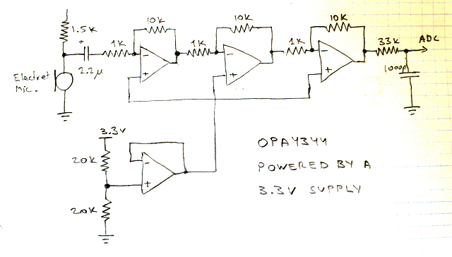
The Analog Amplifier and Low-Pass Filter
The analog input section is built around a quad opamp,
OPA4344. This is a low-voltage rail-to-rail opamp. The exact
specifications are not critical in this circuit, but the ability to
swing the output all the way at low supply voltages is useful, because
it allows the ADC to use its full range.
I used all the 4 opamps in the package, but the circuit is
really almost as simple as it gets. I used three opamps in identical
inverting-amplifier configurations, each with a gain of 10. The fourth
was used to generate the mid-supply bias voltage for the other three.
The RC low-pass filter sits between the output of the last amplifier
and the ADC input pin of the MSP430. The only other components are an
electret microphone connected by a 1.5k resistor to the 3.3V supply and
by a blocking capacitor to the input of the first amplifier.
It should be possible to feed the ADC using one or two opamps,
but I had a quad package so I used all the opamps in it. I also wanted
to keep the circuit simple enough that I would understand it
completely. I am sure that it is possible to build much better analog
sections from the 4 opamps in the OPA4344.
Producing Sound
The device can also produce sound. My objectives were to
produce a strong sound with most of the energy at a fixed precise
frequency that other similar devices would be able to detect. Although
there are pretty small speakers, a speaker is not a good choice for
such a device. A speaker is designed for fidelity. Therefore, to get
most of the energy at a single frequency you need to feed the speaker
with a sine wave. A microcontroller is not good at producing sine
waves; it is good at producing square waves.
There are several ways to produce sine waves. One is with a
separate oscillator. It would require tuning to get the correct
frequency. Another option is to let the processor produce a square wave
and to pass the signal through a low-pass filter (a sqaure wave is a
sum of sines in the fundamental frequecy and its harmonics; we need to
filter the harmonics). In either case the sine would require
amplification to produce a strong sound from a spkeaker.
A better option is to use a device called a sounder. There are
two kinds: piezo sounders and electro-magnetic ones. I used an
electro-magnetic sounder. These are basically tiny speakers. They have
a response curve with high peaks, so they do not reproduce sound
accurately. Instead, they tend to resonate mechanically when excited.
You can excite them with a square wave and still get a very clean
sine-wave audio output.
The sounder I used is called QMB111PX from Star Micronics. It
is designed to resonate at 2048Hz, but tends to resonate at 4096Hz.
When I drive it with a 4096Hz square wave, it produces a very clean
sine output. But I do not want a 4096Hz output because it is at exactly
half the sampling frequency. I want a 2048Hz sound. When I drive it
with a 2048Hz it produces a combination of 2048Hz and 4096Hz. How much
of each depends mostly on how the sounder is mounted. The volume of
sound also depends on the mounting.
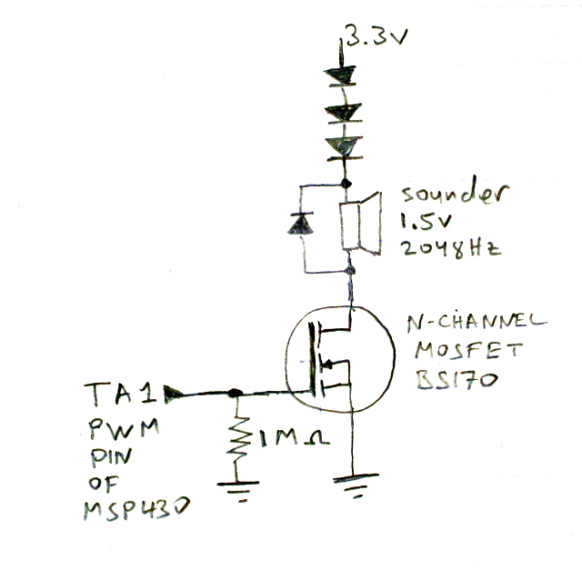
The MSP430 cannot drive the sounder directly. I used a MOSFET
transistor (BS170) to switch the sounder. You also need a
reverse-biased diode across the sounder, to protect the transistor from
the inductive load of the sounder. The sounder that I used is designed
for 15-2V, so I used 3 diodes in series to drop about 1.8 of the 3.3v
supply voltage before it hits the sounder.
It is possible to replace the MOSFET transistor by an
NPN transistor. It would draw some base current from the
MSP430, but it works. (You need a current-limiting resistor between the
pin of the MSP430 and the base of the transistor.)
I am hoping to find better sounders. There are 3 ways to do
better than the QMB111PX: (1) a sounder that does not produce a strong
harmonic at 4kHz, (2) a sounder that runs directly on 3.3V without the
need to drop down the voltage to 2V, and (3) a sounder that uses less
power, perhaps a piezo one. I'm investigating.
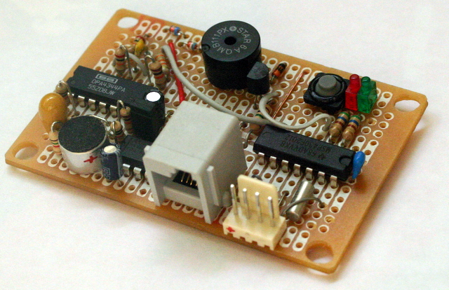
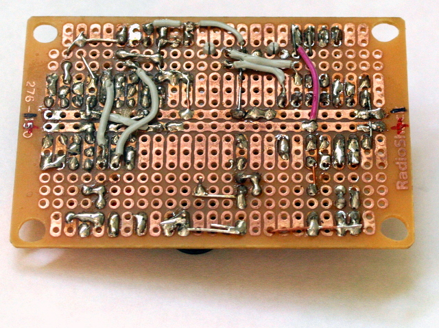
Construction
I constructed the circuit on a Radio Shack prototyping board.
The sides of the board are multiple of 8mm, but the mounting holes are
too small for Technic axles/pins, and their centers are a bit too far
apart. I enlarged the mounting holes (very carefully); they
still don't fit Technic axles, but at least they fit Technic pins, and
at the right center-to-center distances.
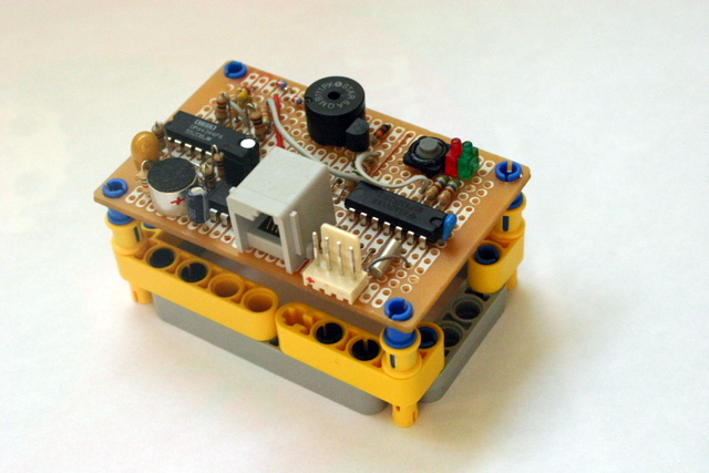
The chip on the right is the MSP430F2012, the one on the left is the
quad opamp, and the one near the NXT socket is the MAX604 voltage
regulator. The small silver cylinder is the microphone and the larger
black one is the sounder. I fit a NXT socket on the board. I had to
bend the pins a bit,
but it worked. I drilled holes (with a manual drill) for the mounting
studs of the socket, so it is really secure. You can see them at the
top center of the next figure.
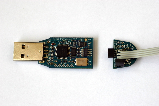
The processor that I used is in a DIP package, not on a
daughter board of the ez430. To program and debug it, I constructed an
extension cord for the ez430. I removed all the components from one
daughter board (including the processor) and soldered instead a 4-wire
flat cable. It connects to 3 of the ez430's terminals directly, but to
the 3.6V power connector through a jumper. This allows me to connect
the ez430 to a circuit that runs on its own power.
I initially left the ez430 and the daughter board with the
extension cord exposed, without the plastic cover. At some point, my
ez430 died completely. I am not sure why, but perhaps it was damaged by
static electricity or by a metal object that caused a short. I bought
another and decided to keep it enclosed. I modifed the plastic
enslosure to allow the extension cable out and to allow accesss to the
jumper pins. So far it works.
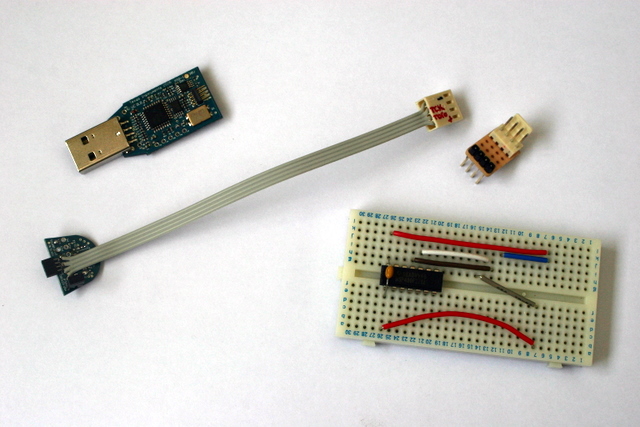
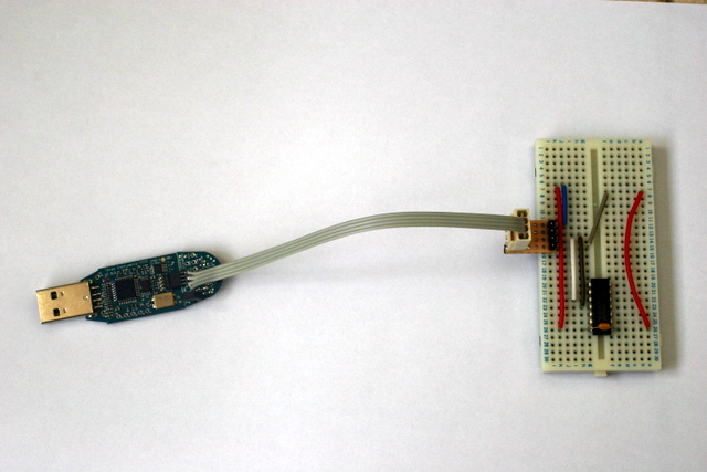
This contraption allows me to build circuits with an MSP430
and to program and debug them in the circuit. The 4 wires from the
ez430 connect directly to the chip. A pull-up resistor on the reset pin
ensures that the chip boots once power is applied when the ez430 is not
connected (when it is, it prevents the chip from booting).
A MAX604 produces 3.3V from the NXT's 4.3V. To allow the
circuit to run with power from the ez430 (or from a pair of AA
batteries; it still detects the tone and lights a green LED when it
does!), I connected the output pin of the MAX604 to the rest of the
circuit through a jumper.
In the pictures below you can see the extension cord that I built
for the ez430, an F2012 in a breadboard ready to be connected to the
ez430, and the F2012 connected to the ez430.
Algorithm Prototyping with a PC
The algorithm that the MSP430 runs is not trivial to get
right, especially when fixed-point arithmetic is used. I didn't try to
develop the algorithm directly on the MSP430. Istead, I first developed
a version in Matlab (a numerical computing environment). The graphs
that appeared above were produced by this prototype. I first developed
the algorithm in floating point. When it was working, I created a
fixed-point version and explored its behavior. I first tested the codes
on synthetic sine waves produced in Matlab, and then on recordings of
actual sounds from a buzzer (similar to a sounder, but with an internal
circuit, so it produces sound when connected to DC).
When the Matlab program was working properly, I converted it
to a C program for the MSP430. Every time I optimized the MSP430
program, I made a similar change in the Matlab program to ensure that I
still get correct results.
I also used Matlab to analyze the audio from the sounder and
from other devices that I tried, to assess whether they produce the
right frequency and to assess how clean the sound is. To do that, I
wrote a little Matlab program that recorded a bit of audio from the
laptop's microphone, then computed the FFT of the result and presented
it graphically, then repeating.
The Tradeoffs associated with the Crystal Oscillator
The F2012 has several oscillators. They are used for
clocking both the processor and the peripherals, including the timers.
One is a digitally-controlled oscillator (DCO) that can be set to 1, 8,
12, or 16MHz, the second is a 32kHz crystal oscillator, and the third
is a very low-frequency oscillator that is irrelevant for this
design.
I clocked the timer from the 32kHz (more precisely, 32,768Hz)
oscillator, which requires an external crystal. This allows the system
to sample at an accurate rate, so its center detection frequency is
both stable and accurate, and the tone that it produces is at an
accurate frequency.
The main disadvantage of this setup is that the 32kHz does not
allow you to sample at a rate higher than 32kHz and does give much
flexibility in the tone that it generates. Even sampling at 32kHz is
hard; I had to use two different interrupt routines to wake up the ADC
(sampling at 8 or 16kHz is easy).
If you connect the timer to the DCO, which I run at 16MHz to
do the signal processing fast enough, you have a much more flexibility
in choosing the sampling rate and in terms of generating tones. In
particular, it should be possible to sample at 64 or even 128ks per
second, which would improve anti-aliasing even further. The
disadvantage of using the DCO is accuracy; its frequency is only
accurate to within 6%, if you take into consideration calibration
errors and frequency dependence on temperature and supply voltage. This
is a pretty wide range of possible clock frequencies, which would make
reliable tone detection difficult.
Perhaps the best design is to use the DCO to clock the timer,
but to calibrate the timer using a crystal oscillator. The F2012 has
two timers; a general-purpose timer and an interval/watchdog timer. You
would use the DCO to clock one and the 32768Hz crystal oscillator to
clock the other. This would allow you to use the crystal oscillator to
determine the exact rate at which the DCO oscillates. It might work,
but it's a pretty complicated approach.
Many other MCU's in the MSP430 family (as well as in other MCU
families) can be clocked by a high-frequency (several MHz) crystal
oscillator, which would eliminate this tradeoff altogether.
Software
Here is the software that I wrote for the device:
- The Matlab program that generates the coefficients and which tests the algorithm. This file is not cleaned up.
- The C program that runs on the MSP430F2012 and the file with the coefficients.
The program starts by repeatedly performing the Goertzel algorithm and
displaying the result using a green LED. It also listens as a slave to
the I2C channel. If the master tries to read, it sends
9 bytes: two 32-bit integers representing the overall sound energy and
the sound energy near 2048Hz, and a one-byte sequence number of the
measurement. The sequence number allows the I2C master to know whether it is reading the same measurement twice. The I2C
master can also send the device 3 commands: to start sounding a 2048Hz
sound, to stop the sound, and to start monitoring sound again. You can
also start and stop the sound from the button on the device itself. The
code should compile under both IAR Embedded Workbench and under Code
Composer Essentials (but my final tests where under IAR, which seems to
produce much more compact code).
- The RobotC program that runs on the NXT as an I2C
master. The program repeatedly reads the data from the device and
displays it, but if you press the center (orange) button it tells the
device to sound a tone instead. When you release the button, the sound
stops and sound monitoring resumes.
- An NXC program that does the same thing. It does not run correctly under the standard firmware (version 1.04), because it has bugs in multibyte I2C transactions. It runs without a problem with John Hansen's improved firmware.
An Alternative Analog Design
When I first thought of building an audio two-way signaling
device for the NXT, I thought of using mostly analog devices, not
digital signal processing.
The LM567 is a single-purpose chip that detects whether a
single frequency is presentin the signal that you feed it. It runs on
5V, and there is a 3.3V version called the LMC567. You program the
frequency that you want to detect using resistors and capacitors. It
should be fairly easy to build a device similar to mine around this
chip. You would still need a microphone amplifier, but that's pretty
much it. The LM567 produces a digital output present/not-present signal
that you can communicate to the NXT using an I2C interface chip, or
simply through the analog sense line. To produce the tone, you could
use any oscillator circuit. This analog device would not be as accurate
as my device (my devices accurate depends on that of a crystal
oscillator, which is good), and it would not be easy to change the
tuned frequency. You could change it with a trimmer, of course, but it
would be hard to change it from the program. One way to detect multiple
frequencies with the LM567 is to use several of them, each tuned to a
different frequency. Another way is to use an I2C potentiometer to
adjust the center frequency.
The cost of this solution is a little lower than that of mine,
but not by much: Digikey charges $1.80 for the LM567 ($1.89 for the
LMC567) and $2.70 for the MSP430F2012. So the versatile MCU is more
expensive than the special-purpose analog chip, but not by much.
The main advantage of the analog solution is that it is
probably a lot easier to develop and to debug, because there is no
software involved.
More on Parts
If you build something like this, you may be able to use parts
salvaged from broken or obsolete circuits. Electromagnetic sounders are
fairly common. In my home we had 6 or 7 dead analog alarm clocks, and
all of them had sounders similar to the one I used. PC motherboards
also use these devies. If you use a salvaged sounder, check whether it
indeed produces the tone that you need. 32768Hz crystals are also
common in battery-operated alarm clocks and in motherboards. The
crystal the I used is from a dead motherboard.
The opamp that I used (OPA4344) is a pretty expensive one, at
more than $4 at Digikey, but you can build a similar circuit
from cheap opamps like the LM324.
Finally, I used a 3.3V regulator in the circuit, but neither
the MSP430 nor the opamp need a regulated supply. The MSP430 needs a
supply voltage of at most 3.6V, so you can't power it directly from the
4.3V supply of the NXT. But you can use a Zenner diode or a few common
silicon ones in series to get the voltage to the correct range. If you
use a higher supply voltage for the opamp than for the MSP430, make
sure that the analog input to the MSP430's ADC does not exceed the
supply voltage of the MSP430.
© 2007, Sivan Toledo