April 2008 update: Jonathan Oakley overhauled my code, fixed bugs, and added features. Here is his version of the code (or search in the repository in www.nxtasy.org for an even more up-to-date version).
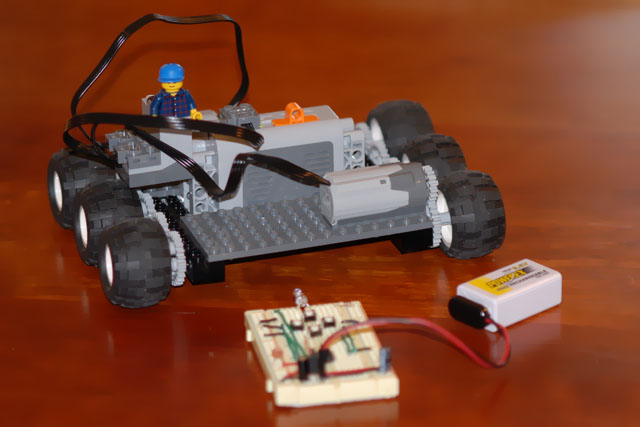
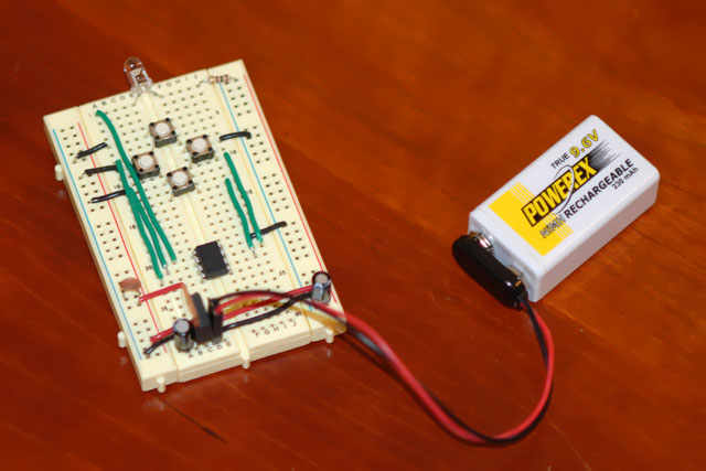
November 2007 update: Pat Hanrahan built a Power-Functions compatible remote control using an ATtiny13 AVR microcontroller on a breadboard. Here is his C program and his makefile. My code is more messy, but here it is if you need it. Here are two pictures of Pat's creation:
|
|

In this project I created an infrared (IR) link that provides bi-directional communication between the NXT and the new Power-Functions system, which consists of a battery box, motors, a remote control (an IR transmitter) and an IR receiver that controls the motors.
I previously built an IR transmitter for the NXT which used an MSP430 microcontroller and which was able to send Sony IR commands (the specifications of this protocol are widely available). In this project, I wanted to achieve three additional goals:
I should point out that commercial IR links for the NXT are available from both HiTechnic and Mindsensors. Both are capable of sending commands to the Power-Functions receiver (as well as to the RC Trains receiver) and of bi-directional communication with the RCX. I do not think that they can receive transmissions from the remote controls of the Power-Functions and the RC Trains, but these vendors could have certainly added that capability. Also, at least in the HiTechnic IR link, the NXT can only tell it to send a single Power-Functions command. This means that the NXT needs to repeatedly send commands to the IR Link if it wants to keep a Power-Functions motor running (because the Power-Functions receiver will turn the motor off if it does not hear from the transmitter for couple of seconds). My IR link can repeatedly send the same IR command over and over again, to keep a motor running with no further NXT action; building my own link allowed me to experiment with the communication protocol.
Warning: connecting your NXT to any home-made gizmo (like the one described here) can damage it. Beware.
The ATmega48, ATmega88, and ATmega168 are 8-bit microcontrollers from the AVR family. The are identical except for their memory sizes. They have two useful features compared to smaller AVR's that made them appropriate for this project. The first is a 16-bit time/counter with a capture capability, and the second is a UART, a peripheral that allows serial communication with a PC.
None of these is essential for the functionality of the device. I could have used an 8-bit timer instead of the 16-bit one, incrementing a high-order byte on overflow if necessary. A general-purpose interrupt could have been used instead of the capture functionality of the 16-bit timer; this would have introduced more errors into the period measurements (due to the time to invoke the interrupt and for the processing time of the interrupt service routine), but with a high clock speed these errors would be small.
The ability to print data out to my PC through the UART made the analysis of the infrared protocol relatively easy. I would not want to do this project without this capability, but once the project is complete, I probably won't use the UART any more. If I were producing these devices, I probably would have switched to a smaller AVR with no UART and a smaller memory when prototyping was over.
I used an AVR Dragon to program the ATmega88. The Dragon is a USB programmer/debugger. It can program the AVR using several different protocols, and it can also be used to conduct in-system debugging of an AVR. It costs less than $50, so it packs a lot of functionality for a modest price. However, it turns out to be a very sensitive device. Several people reported Dragon deaths on AVR Freaks, and at least two designed adapter boards to protect it from the system it programs or debugs.
Well, I also managed to kill my Dragon. I am not sure what I did wrong (if anything), but it died. Windows still recognizes it, but AVR Studio fails to communicate with it. I was too lazy to build a complex adapter board, so I followed a simpler advice from an AVR Freaks forum: to protect the signal lines connecting the Dragon to the target with 220 Ohm resistors (I actually used 330 Ohm ones). This seems to work fine and second dragon is still alive.
I only used the Dragon so far to program the AVR using the ISP programming protocol. I didn't use the other programming protocols and I didn't used the debugging protocol. Therefore, it might have made more sense to purchase the AVR ISP programmer instead; it is even cheaper but much more protected than the Dragon.
I built the prototype in stages. The first stage contained just the AVR and an infrared detector, plus bypass capacitors.
I first tried to build the circuit on a breadboard. It didn't work. The AVR kept reporting that the detector was detecting signals even when no infrared remote was around. A quick inspection of the signals using an oscilloscope showed that when the detector and the AVR were connected to the same power supply, the detector generate spurious detections. Without the AVR, the detector worked just fine. So noise from the AVR was confusing the detector.
Breadboards are notorious for propagating and picking up noise, so I just removed the components from the breadboard and soldered them to a prototyping board. Now the circuit worked fine.
The first prototype used the AVR's internal RC oscillator. I wanted a more stable oscillator, to make infrared communication more robust, and to enable high-speed serial communication with my PC. (With the RC oscillator, I could communicate at 1200 b/s, but not at higher rates.) So I added a 14.7456 MHz crystal and the two required capacitors for it.
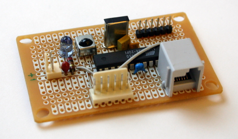
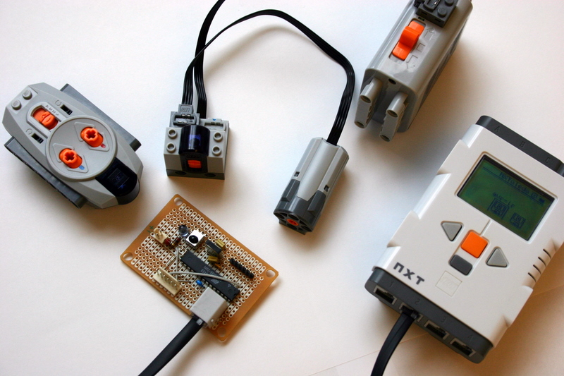
In the picture above you can see the complete device (some details are described later). On the left there is a 2-pin power connector that I use to power the circuit from an AC adapter rather than the NXT. The white 6-pin connector on the botton connects the circuit to an AVR programmer (using the ISP programming mechanism). The gray connector next to it connects the device to the NXT. The 6 header pins on the top right connect the circuit to a serial port. To connect a microcontroller to a serial port of a PC you need a level converter. In this case, it is not on this board but on a separate one that plugs into these headers. The other components in the circuit are one tantalum and two ceramic filtering capacitors, an IR LED (with a current-limiting resistor below it), the IR detector (next to the LED), a crystal and its two required capacitors, and the AVR itself. There are also two pull-up resistors between the AVR and the NXT connector that you can't see in this picture.
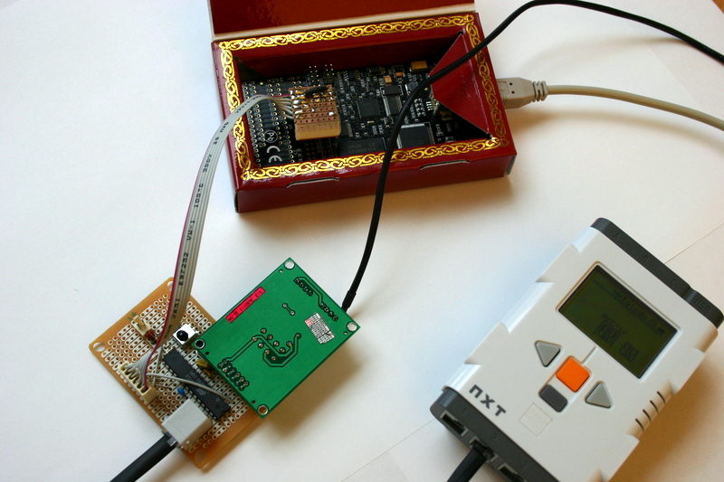
In this picture you can see the development environment for this device. On top you can see the dragon. The little home-made board contains a connector on the other side and the current-limiting resistors. The USB cable goes through a hole that I made in the cardboard box of the Dragon. I normally use it with the lid closed, to further protect it. The green board contains an RS-232 level shifter chip (on its other side) that allows the AVR's UART to talk to a serial port of a PC. Finally, the NXT is used to test the I2C communication.
Now it was time to actually measure and analyze some infrared signals.
I started to decypher the Power-Functions infrared protocol by measuring the signals that the IR detector picked up from the remote control. The detector that I used (Radio Shack 276-640) detects infrared signals modulated at 38KHz with light wavelength 940±50nm; but these detectors tend to detect most infrared remote-control signals, even if the modulation frequency is a bit different. The diagram below shows the signals that I measured when I pressed the red button in the forward direction when the remote was set to channel one. Each line represent a burst of signals, with time going from left to write. Each black rectangle represents one detection, and the width of the rectangle represent the length of time the signal was detected. The horizontal distance between rectangle represents the length of time between detections. After each burst of 18 detections, the detector did not detect anything for a fairly long period, and then detected another burst. Each burst is represented in the diagram by a row of rectangle.
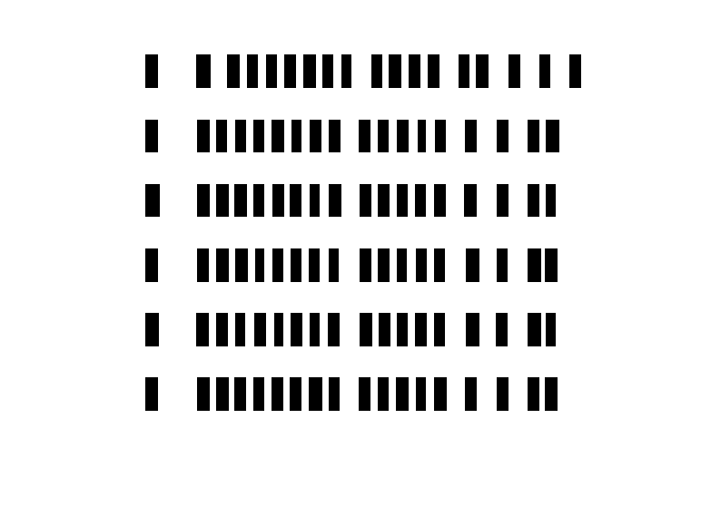
These measurements allowed me to determine the representation of commands in the protocol. The transmissions consist of signal periods of roughly the same length separated by no-signal periods of varying lengths. The first no-signal period is always the the same length and much longer than all the others. This appears to be some sort of a start-condition indication that does not convey any information (apart from allowing the received to distinguish between this protocol and others). Following that, each short period represents a zero bit and each long one represents a one bit. It could also have been the other way around, but the full analysis of the bit sequences, described bellow, supports this hypotheses. Altogether there are 16 bits in each burst.
I generated histograms of the four relevant periods of this protocol: the signal period, the initial no-signal period in each burst, and the short and long no-signal periods representing bits. I estimate the average signal period to be about 60 clock ticks (), the initial no-signal period to be about 215 ticks, the zero no-signal to be 40, and the one no-signal to be about 110.
Before moving on to the actual meaning of the bits, I wanted to know how the bursts are spaced. Here is a another sequence of detections, already translated into zeros and ones. After each burst the program printed the length of time from the end of the previous burst. This sequence represents a longer press of the same key.1000000100010111 130537
1000000100010111 14976
1000000100010111 14839
1000000100010111 23711
1000000100010111 23709
1000000100010111 23786
0000000100001110 29087
0000000100001110 14852
0000000100001110 14923
0000000100001110 23689
0000000100001110 23694
We can see that the remote sends repeatedly the same command. The first 6 commands tell the receiver that a particular button is pressed, and the last 5 tell the receiver that buttons are no longer pressed. Each sequence starts with 3 repetitions about 14,900 counter ticks apart. After that, repetitions are spaced further apart. The first repetitions may be spaced closely to allow the receiver to quickly respond even if the first transmissions are lost or corrupt. The wider spaceing after that may be designed to reduce power consumption by the transmitter.
Now let's examine the bit sequences that the transmitter sends. There are four buttons no the remote, and when you release them, the remote sends a "no button pressed" command for a short while. Here are the single-press and no-press command sequences for the 4 channels. I split the bits into groups that seem to represent different fields; see below for what the fields appear to mean.
channel 1 red forward 1 0 00 0001 0001 011 1
channel 1 red reverse 1 0 00 0001 0010 010 0
channel 1 blue forward 1 0 00 0001 0100 001 0
channel 1 blue reverse 1 0 00 0001 1000 111 0
channel 1 no buttons 0 0 00 0001 0000 111 0

channel 2 red forward 1 0 01 0001 0001 011 0
channel 2 red reverse 1 0 01 0001 0010 010 1
channel 2 blue forward 1 0 01 0001 0100 001 1
channel 2 blue reverse 1 0 01 0001 1000 111 1
channel 2 no buttons 0 0 01 0001 0000 111 1

channel 3 red forward 1 0 10 0001 0001 010 1
channel 3 red reverse 1 0 10 0001 0010 011 0
channel 3 blue forward 1 0 10 0001 0100 000 0
channel 3 blue reverse 1 0 10 0001 1000 110 0
channel 3 no buttons 0 0 10 0001 0000 110 0

channel 4 red forward 1 0 11 0001 0001 010 0
channel 4 red reverse 1 0 11 0001 0010 011 1
channel 4 blue forward 1 0 11 0001 0100 000 1
channel 4 blue reverse 1 0 11 0001 1000 110 1
channel 4 no buttons 0 0 11 0001 0000 110 1
Before we move on to dissect these commands, we also need to look at the commands that the transmitter sends when you press two buttons at the same time.
channel 1 red-fwd blue-fwd 0 0 00 0001 0101 101 1
channel 1 red-fwd blue-rev 0 0 00 0001 1001 011 1
channel 1 red-rev blue-fwd 0 0 00 0001 0110 100 0
channel 1 red-rev blue-rev 0 0 00 0001 1010 010 0

channel 2 red-fwd blue-fwd 0 0 01 0001 0101 101 0
channel 2 red-fwd blue-rev 0 0 01 0001 1001 011 0
channel 2 red-rev blue-fwd 0 0 01 0001 0110 100 1
channel 2 red-rev blue-rev 0 0 01 0001 1010 010 1

channel 3 red-fwd blue-fwd 0 0 10 0001 0101 100 1
channel 3 red-fwd blue-rev 0 0 10 0001 1001 010 1
channel 3 red-rev blue-fwd 0 0 10 0001 0110 101 0
channel 3 red-rev blue-rev 0 0 10 0001 1010 011 0
channel 4 red-fwd blue-fwd 0 0 11 0001 0101 100 0
channel 4 red-fwd blue-rev 0 0 11 0001 1001 010 0
channel 4 red-rev blue-fwd 0 0 11 0001 0110 101 1
channel 4 red-rev blue-rev 0 0 11 0001 1010 011 1
Time to figure out what these bits actually mean. The first thing to note is that two fields never change. The second one (one bit, the second one from the left) is always 0, and the fourth one is always 0001. There is no way to know what these fields mean. Perhaps they represent part of a more general protocol, but on the Power-Functions transmitter, they are always the same.
Next, the number of ones in these transmissions is always even. This suggests that one of the bits is a parity bit. I think it's the last (rightmost) bit.
Two other fields have obvious meanings. The third field (two bits) represents the channel number, encoded in binary, starting from zero. The sequence 00 (zero in binary) represents channel 1, the sequence 01 channel 2, 10 for channel 3, and 11 (three in binary) stands for channel 4. The fifth field tells the receiver which button is pressed. The fields has 4 bits, one for each button of the remote: red-forward (rightmost bit in this group), red-reverse, blue-forward, and blue-reverse.
The first bit in the transmission appears to encode the parity of the number of buttons pressed. It is zero when no buttons are pressed and when two are pressed, and it is one when only one button is pressed.
The sixth group of bits is a mystery. For each button combination these bits have a particular setting in channels 1 and 2, but a different one for channels 3 and 4. For example, when the red-forward button is pressed these bits are 011 in channels 1 and 2 but they are 010 in channels 3 and 4. Perhaps it's part of some error detection and/or correction code.
In 2006, Lego intruduced a line or remote-controlled trains (RC trains), also using infrared. Earlier this year, I made some measurements of the signals of the RC-trains transmitter; they appear to be similar in structure. But I don't have the transmitter with me, so I can't make systematic measurements.
Once the structure of the transmission became clear and I had a catalog of all the different command codes that the transmitter sends, I could attempt to transmit commands to the receiver.
I added to the circuit an infrared LED (Radio Shack 276-143) and connected it through a current limiting resistor to a pin of the AVR. This LED emits light at a 940nm wavelength and can sustain up to 100mA of current. Since I connected it to the AVR directly, I can only drive 40mA through it (the limit for the pins of the atmega88). I actually limited the current to about 20mA. To drive the LED at more than 40mA (to achieve higher transmission range), you can switch it using a transistor.
To generate the approximately 38kHz signal that the LED needs to transmit, I used Timer 0 of the AVR, operating in a pulse-width modulation (PWM) mode. I configured its prescaler to divide the 14,745,600 Hz frequency by 8. This gives 48.5 clock ticks per cycle, which is enough to get close to the correct frequency but no too much to overflow the 8-bit counter that Timer 0 uses. I set Compare Register A to 48 and Compare Register B to 20. The timer is set in a mode in which it counts from 0 to the value in Compare register A and then resets to zero. A pin called OC0B (Output Compare Zero B) goes low every time the timer is set to zero and goes high every time the timer reaches the value in Compare Register B (20). So we get at this pin a square wave of about 38 kHz and a duty cycle of a little less than 50%.
This signal needs to be delivered to the LED when the infrared protocol needs to send a signal, but the LED needs to be turned off when the protocol is at a no-signal period. This is done by configuring the timer to emit or not emit its signal on pin OC0B. When no signal is emitted, we set the pin to low, to ensure that the LED is turned off.
The command is sent using a state machine and two shift registers. The state machine has special states for the first two signal periods, for the long initial no-signal period, and for the signal and no-signal periods that follow. One shift register (a 16-bit variable) initially stores the command to be sent, and the other store all ones. Every time we need to determine the length of the next no-signal bit period, we check the most significant bit of the command variable, and we shift it left by one bit (for the next bit). We also shift the all-ones shift register at every bit, and when it is zero, we know that we have transmitted all the bits.
The lengths of the periods is controled by Timer 1 of the AVR. This is a 16-bit timer that can generate the relatively long quiet periods between command bursts. It is configured to count up and to generate an interrupt every time the timer matches the value stored in Compare Register A. At the start of each period, we set the timer to zero and set the Compare Register A to the length of the period. When the interrupt is invoked, we connect or disconnect the output of Timer 0 from the output pin connected to the LED, and set the next period.
The signal that we send is not exact, because the interrupt processing has some latency. But since the processor runs at over 14 MHz, these in accuracies are small.
The receiver picks up the signals without any trouble!
Once the system was transmitting IR signals that the Power-Functions receiver responds to, it was time to try to use I2C to control the IR link. I added a NXT socket to the circuit and pull-up resistors and added code to the AVR program to send and receive data via the I2C bus, as a slave.
The AVR listens to the I2C bus and responds to both writes from the master (the NXT) and to read requests. When the NXT writes, the AVR interprets that as a request to send an IR command. These requests consists of 3 bytes: one byte specifies the protocol to be used, and the other two are the 16 bits of the transmission. The protocol byte currently tells the AVR whether to send the request once or repeatedly. By requesting a repeated command, the NXT can keep a Power-Functions motor turned on indefinitely using a single command to the AVR. The main drawback of this is that if the program on the NXT stops, the AVR does not know about this so it continues to send IR commands to the Power-Functions receiver, which continues to run the motor. But it's more elegant than sending commands from the NXT repeatedly to keep a Power-Functions motor running.
When the AVR is not busy sending IR commands, it listens to incoming IR commands. When the NXT issues a read request, the AVR sends the last IR transmission it received. The AVR only sends a command once; if the NXT queries it again before a new IR command is received, the AVR responds with a message that tells the NXT that no new IR transmissions have been received.
In my earlier I2C gadgets, I sometimes connected the two pull-up resistors via jumpers to the supply voltage. This allows me to disable the pullups when I connect more than one device to a single NXT port. The NXT's processor is connected to the I2C lines through a current-limiting resistor, so when the combined resistance of the pullups on all the devices is low, the NXT cannot drive the I2C lines low enough. This is why Lego specified an 82k resistors for the pull-ups. (Thanks to Philo for clarifying this.)
The commercial sensors from Mindsensors can configure the pull-ups automatically with no jumpers. If you enable this feature (which is turned off by default), the sensor will decide on its own whether to use pull-ups (if there are no other pull-ups on the I2C lines), or to disable them if it detects external pull ups.
I decided to try this out. Instead of connecting the pull-ups to the supply voltage, I connected them to a free pin on the ATmega88. Initially, I set this pin to high, to pull up the I2C lines. Once everything was working, I developed the automatic configuration mechanism.
It works as follows. When the AVR boots, it enables its analog-to-digital converter (ADC), which can measure analog voltages on some of its pins, including the I2C pins. I then set the pin that is supposed to pull up the lines to low (near 0 volts) and I measure the voltage on one of the I2C lines. If the voltage is near 0, it means that there are no other pullups on the I2C lines, so I enable the pull ups by setting the pull-up pin to high. If the voltage is not near zero, then some external circuit is pulling the lines up, so I disable the pull-ups. The pull ups are disabled by configuring the pin to which the resistor are connected as an input pin. In that state it does not pull the I2C lines but instead follows their transitions.
Apart from small bugs, the main difficulties that I encountered in this project are the spurious infrared detections on the breadboard and the slaying of one Dragon. I solved the first problem by soldering the circuit on a prototyping board and the second by using current-limiting resistors on the Dragon's signal lines.
The end result of the project is a device that can receive Power-Functions infrared transmissions, can send them (once or repeatedly), and can also record and trasfer to a PC the patterns of unknown infrared remote-control signals. The AVR processor that I used here runs directly on the voltage that the NXT supplies to sensors, and it is supported by a good free C compiler (GCC).
© 2007, Sivan Toledo